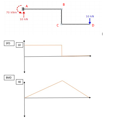
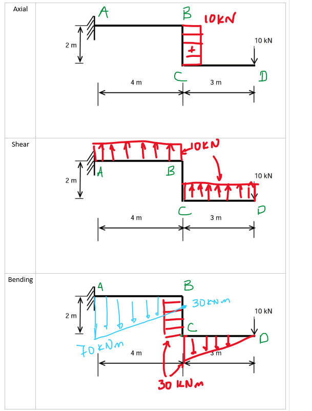
Today I came across this question and I can't sleep thinking about how to solve it. How do I find the principal values and sketch a shear force and bending please see my attempt as I'm not sure if this is correct. diagram on the below picture? 
-
$\begingroup$ Welcome to Engineering Stack exchange. To prevent your question to be closed you can post what you've tried. As of now it will probably be considered as a homework question and probably closed. Btw one good tool to help with the results is ftool (one free program), check the results into the program and try to work the equations backwards (your example is pretty straightforward with the results) $\endgroup$– LeafkCommented Nov 17, 2020 at 1:49
-
$\begingroup$ Could you explain what you mean by principal values? $\endgroup$– NMechCommented Nov 17, 2020 at 6:12
-
$\begingroup$ @NMech I think principal values are forces at points of interest. Ignore if this is not applicable since I can see there is only one force acting to the right and not sure about if a reaction force is acting on the left. $\endgroup$– FilCommented Nov 17, 2020 at 6:44
-
$\begingroup$ @LeafK please see updated. $\endgroup$– FilCommented Nov 17, 2020 at 12:49
2 Answers
So, in such problems, the first thing to do is calculate the support reactions. Thankfully you've already done that correctly, so we can move on from there.
Now, something to keep in mind when trying to figure this sort of thing out is the fundamental equation of Euler-Bernouilli Beam Theory:
$$\dfrac{\text{d}^2}{\text{d}x^2}\left(EI \dfrac{\text{d}^2w}{\text{d}x^2}\right) = q$$
or, in English, we must remember that shear forces are the integral of the applied loading and bending moment is the integral of shear (and more, but this is what's relevant to this problem).
So, let's take a look at your expected solution, adding some names to the points of interest:
There are a few problems which are immediately apparent:
- your moment diagram is zero at the support, but we know that it must be 70 kNm from the reaction
- you show zero shear in CD, but a bending moment going from 0 to 40 kNm in the same segment. However, if we remember that bending moment is the integral of shear, that makes no sense: if shear is constant at zero, that means the slope of the bending moment must also be zero. So at least one of those diagrams is wrong
- You also have a change in the slope of the bending moment, from positive (as in, getting further away from zero) in CD to negative (moving towards zero) in AB. This would imply in a change of sign in the shear stress. Since the change in the slope of the bending moment is instantaneous, this would be equivalent to a discontinuity in the shear diagram. And since shear is the integral of the applied loading, this would imply in a concentrated force at that point, which we don't have.
So, let's try again.
Let's start with the shear diagram. We know that it's the integral of the applied loading $q$. In this case, however, $q(x) = 0$ everywhere. So we know the shear force will be constant everywhere. But constant and equal to what?
Well, while $q(x) = 0$ everywhere, it does have concentrated forces at A and D, which cause discontinuities in our shear diagram. So we know that the shear at A and D will be equal to 10 kN at those points (let's not think about whether that's positive or negative for now). And we've already concluded that the shear is constant throughout since $q(x) = 0$, so I guess that means the shear diagram is simply 10 kN everywhere, right?
Not so fast.
In this case, we have the complication caused by the vertical segment BC. To handle this, we need to remember what the applied force this structure is supporting is. It's a vertical force. This vertical force is resisted by the horizontal member CD, but the force being resisted is vertical nonetheless. Wherever you are in the structure, all if it is supporting a vertical force.
And does a vertical force cause shear in a vertical element? Obviously not. It causes an axial load.
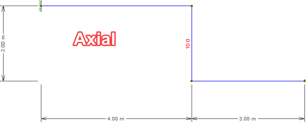
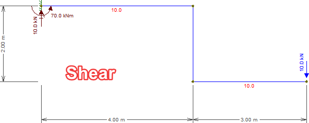
So what we end up having in this case is a shear diagram which is equal to 10 kN in AB and CD, but zero at BC, and an axial diagram which is zero at AB and CD but 10 kN at BC.
This doesn't break with the rule that shear must be constant when $q=0$ because the instantaneous change in direction that happens from AB to BC and from BC to CD behaves in exactly the same way as a concentrated force: it causes a sudden change to how the beam behaves under the external load: the horizontal segments resist it through shear, the vertical segment through axial. The direction of the internal force itself is always vertical, and that's what really matters. If BC weren't vertical but inclined, then we'd instead see only a drop in the shear diagram as some of the shear is transformed into axial. If BC were curved, then the shear diagram would change according to the tangent at any given point.
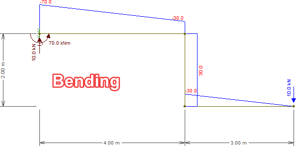
And so we move on to the bending moment diagram. This can be done by simply integrating the shear diagram. CD is 3 m long and suffers a constant shear of 10 kN, so the bending moment at C is of course equal to $3 \times 10 = 30\text{ kNm}$. Notice this is also what you get from simply calculating the bending moment caused by D on C (just as you did to calculate the moment reaction at A). That's not a coincidence, it always holds true.
Indeed, think about what the reaction moment would be if AB were only 3 m long. In that case, the horizontal lever arm from A to D would be six meters, so the support's bending reaction would be 60 kNm. The bending moment is always 10 times the horizontal lever arm. And that also applied for the beam itself! The bending moment is always 10 times the horizontal distance from the desired point to D.
So, the bending moment at D is zero, at C, 30 kNm, at B, also 30 kNm, and at A it's the same as the reaction, 70 kNm. Basically, as far as the bending moment is concerned, that vertical step at BC is entirely irrelevant: the bending moment is basically identical to what it'd've been without BC (i.e. a simple cantilever).
Now, lastly, we need to talk about signs. Below we see the standard sign convention:
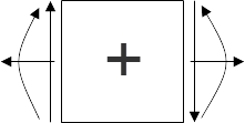
This shows the direction of positive internal forces depending on whether you're looking at the left or right side of the section.
We can see that a downward force to the right or an upward force to the left are both considered positive in shear. Since that's the case throughout the structure (being pushed down by a force to the right and pushed up by the support to the left), our shear will be entirely positive.
The downward force will obviously put BC in tension, which is positive in our convention.
However, the force creates a clockwise rotation to the right of the structure, which is resisted by the counter-clockwise moment at the support to the left. Both of these are negative in our convention, so we get negative bending moment throughout the structure as well.
And now, to check our work:
Note that though the bending moment plot is above the beam, it has a negative value. That's also standard convention: always draw the bending moment on the side which is under tension.
Results obtained with Ftool, a free 2D frame analysis tool.
The three diagrams (axial, shear, bending) are the following. Axial is required because the section BC (at 4[m] from the left support) is subject to axial stress the way it is oriented.
The sections AB and CD are subjected to shear forces (and the value is constant at 10[Nm]).
Finally, the bending diagram. A quick note, on this diagram don't pay attention to the sign, just on the magnitude. Section AB and CD have a slope in bending moment. While section BC carries a constant moment. For bending moments at points are:
- A: 70kNm
- B: 30kNm
- C: 30kNm
- D: 0kNm
-
$\begingroup$ Thanks for your help, I am having trouble understanding the shear and bending diagrams, could you represent them in 2 dimensions inform of x-y co-ordinates please? I do understand that the sings are insignificant but it would really help enhance my knowledge if indicated. Thank you! $\endgroup$– FilCommented Nov 17, 2020 at 18:58
-
$\begingroup$ Seeing your diagram I understand that you have difficulty with the fact that the beam is not straight. In some respects, the answer me and Wasabi are giving, is indeed in two dimensions, because it takes into account the shape of the beam. I guess the best advice, I can give to you to understand this better, is "section" the problem at different points. E.g. "cut" the beam just after A and calculate the reactions. Keep doing the same for points B (just before and just after), C and D and you will get a better understanding of how these values are obtained. $\endgroup$– NMechCommented Nov 17, 2020 at 20:31
-
$\begingroup$ Also Wasabi's answer is pretty detailed and is (on its own) a lecture for calculating bending moments on a frame. It will be definetely worth your time reading it. $\endgroup$– NMechCommented Nov 17, 2020 at 20:33

