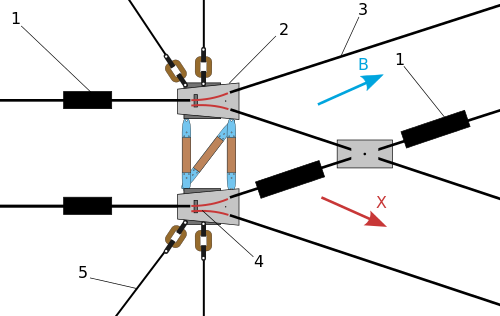
Both methods described above are used. In the first method the boxes numbered #1 are insulating joints. Jumper wires above the overhead tracks provide power to the sections of overhead track isolated by the insulating joints. In the first method, when the bus trolley pole shoes are between the insulating joints and the switch frogs, the electric circuit goes: hot (plus) to the bus via the trolley poles back to the switch and into the switch frog solenoids and then to ground (minus) to throw the switch one way. If the operator is accelerating and/or turning on the heat, then increased current draw throws the switch. After going through the switch frogs the pole shoes hit levers that put the switch frog legs (movable rails) back the way they were originally. To go the other way the operator does not apply power or heat (or cuts power). The current draw is not enough to operate the solenoids so the frog rails stay in the original positions.
In the last method the first (leftmost) boxes in the diagram labeled #1 are special contacts and not insulating joints. If both trolley pole shoes hit the contacts at the same time (for an eventual or ultimate straight through movement here) then a separate circuit is completed to send power to the switch frog solenoids and throw the switch. Again, after the shoes go through the frogs they hit levers to return the frog rails back to the way they were originally. As stated earlier, if the bus has begun a turning movement, one shoe will be ahead of the other. For the contacts lined up in the diagram as shown, the pole shoes will not go through the contacts at the same time and the switch frogs do not get power and the switch remains set for the other branch (for an eventual turn in this diagram). Most installations of this kind I have seen have the contacts staggered so a turning maneuver activates the frogs and a straight through movement does not.
Parts #2 and #4 are the overhead frogs and both are identical. For the switching methods described here there is just one solenoid inside each frog to set the movable rails (switch points) for one direction. The switch "defaults" to the other direction of travel if the solenoid is not given a jolt of power. (Just one solenoid means reduced complexity and weight compared with other switching methods).
