0
$\begingroup$

-- Note: I've flagged this as unlikely to be a quality question. I've refined it and rephrased it as a Mathematics SE focused one instead. Find it here.


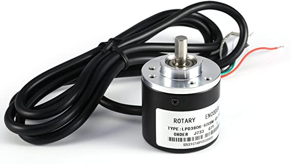
I am using a rotary encoder as a pivot point for a pendulum in a simple actuator mechanism. It is an incremental-only type meaning that it does not have a dedicated signal for absolute positioning, only two quadrature signals for relative motion.

Optical Incremental Rotary Encoder Picture from Amazon store page

(Optical Incremental Rotary Encoder. Picture from Amazon store page)

The encoder is used to detect angular deflection of the pendulum, where bottom-dead-centre will be calibrated to be 0 degrees, clockwise deflection will show as positive angles.

During the startup sequence, the actuator moves back and forth and swings the pendulum slightly (about 45 degrees) and then waits a while for the pendulum to come to a halt naturally. At this point I assume that the pendulum has come to rest at exactly vertically downwards.

Unfortunately, there is a very small amount of static friction in the encoder, which I believe to be due to the grease inside the two ball-bearings. When the pendulum is swinging, this "stiction" is not noticable when swinging rapidly or through a large angle. But when the pendulum is almost coming to a halt, the stiction visibly slows the pendulum and halts it before it has reached bottom-dead-centre. Often the final angle is perhaps 1 degree away from vertical, but this is enough to throw my calibration out.

My first though was to strip it down and swap the bearings out for grease-less ones, but it's an optical encoder and I must not allow any dust inside it as this would compromise the unit's accuracy. So I'm reluctant to disassemble it.

I did try adding a small weight to the end of the pendulum in the hope that it would have greater mechanical advantage over the stiction threshold, and it did improve matters slightly, but adding more weight would reduce the effectiveness of the system.

Is there anything that can be done without disassembling the encoder to reduce the effect of this stiction?

Further info:

The pendulum is an M5 threaded steel rod 210mm in length measured from the pivot to the end.

Removing the pendulum and turning the encoder shaft by hand, it is possible to feel this friction; it feels like a soft click after the shaft has been still for a moment. It is very reminiscent of the shear-force threshold in thick grease. Once the shaft gets moving, it's buttery smooth motion until it comes to rest again.
$\endgroup$

2 Answers 2

1
$\begingroup$

You might be able to wash it out with something like WD40 but that would probably require disassembly. I suspect it might be more resiliant to dust than you think.

Regarding your 45 degrees: as far as I remember from school, the pendulum's period is simple harmonic motion and this is generally an approximation at small deviations from vertical.

I would expect that 45° is not small and that the period will vary as the angle decreases. The encoder is 600 pulses per revolution. You might be able to calibrate to four times that resolution by noting where in the binary sequence the encoder stops.

A B
0 0   0
0 1   1/4 step
1 1   1/2 step
1 0   3/4 step

The encoder is giving a 2-bit Gray code, in effect. Hence the non-standard binary sequence.

$\endgroup$
2
0
$\begingroup$

[This may be similar to what you suggested on your physics.se question, but that seems to be gone now, so I don't know.]

Rather than waiting for the pendulum to stop, and treating that as straight down, I'd wait for the pendulum to settle to something like a 10 degree swing.

Then find the maximum deflection you see on each side of center, and "bisect" that angle to find straight down.

If you want to improve that, measure maximum deflection (on one side) for a couple of successive swings, and see how much the amplitude is reduced between one swing and the next. Let's say we lose 0.2 degrees per swing.

Then we can divide that difference by two, and apply it to the opposite extreme, to extrapolate how far the pendulum would have swung that direction if it were completely friction free. In this case, since we saw a 0.2 degree loss, we expect that without friction the opposite extreme would have been 0.1 degree farther than what we actually measured.

From there, computing "straight down" seems like it would be pretty simple.

$\endgroup$
2
  • $\begingroup$ The damping of the pendulum is non-linear, which makes this much more difficult. I ended up getting practically no response on the Physics SE, so instead of spamming the entire SE network, I reworked the question and posted a new one (with a bounty) on the Mathematics SE here: math.stackexchange.com/questions/4698999/…. $\endgroup$
    – Wossname
    Commented May 18, 2023 at 17:11
  • $\begingroup$ @Wossname: I'd expect it to be non-linear in the long term, but to a limited enough degree that the non-linearity from one swing to the next is minuscule. $\endgroup$ Commented May 18, 2023 at 20:51

Your Answer

By clicking “Post Your Answer”, you agree to our terms of service and acknowledge you have read our privacy policy.

Not the answer you're looking for? Browse other questions tagged or ask your own question.