0
$\begingroup$

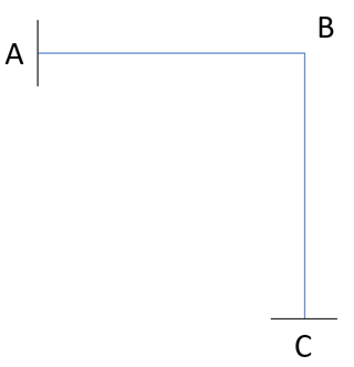
A L-shaped frame $ABC$ (right angle at $B$) consisting of beams $AB$ and $BC$ are fixed at ends $A$ and $C$ to rigid walls. Find the tensile stress at $A$ when the temperature of the frame is raised by $\Delta T$. Properties: length of $AB = BC = L$, flexural rigidity $EI$, coef. of thermal expansion $\alpha$ and circular cross-section with diameter $d$. Also, assume that the right angle at $B$ is maintained during deflection.

enter image description here

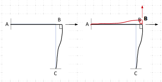
Initial thoughts: due to $\Delta T$, beam $AB$ will cause beam $BC$ to deflect at $B$ rightwards ($\rightarrow$), and $BC$ will cause $AB$ to deflect at $B$ upwards ($\uparrow$).

  1. Since the right-angle remains after the temperature change, the L-shape of the bar is also maintained.
  2. The upward deflection does not influence the tensile stress at $A$.
  3. The thermal expansion of $AB$ ($\delta_T = \alpha \Delta T L$) is counteracted by a reaction force from $BC$, which has the same magnitude of its 'virtual' deflection ($\delta$).

Which leads to

$$\alpha \Delta T L - \delta = 0$$

This is equal to zero because the shape of the beams are maintained.

From the integral method for deflection (or energy method),

$$\delta = \frac{F}{A} \frac{L^3 A}{3} = \sigma \frac{L^3 A}{3}$$

Substituting $\delta$ and solving for $\sigma$

$$\sigma = \frac{3\alpha \Delta T}{AL^2}$$

I am worried that my assumptions are wrong and I cannot think of solving it other way. Could someone check these assumptions? Is there a way that I could do it differently to check the answer?
$\endgroup$

2 Answers 2

1
$\begingroup$

The frame will be deformed as shown below - a distorted L if so claimed.

enter image description here

$\endgroup$
5
  • $\begingroup$ That is right, but I do not understand how the upward deflection will influence the tensile stress at $A$. Do you have any clues? I shall add it to @kamran's tips and try to solve it again. $\endgroup$
    – Iuri
    Commented Mar 22, 2022 at 1:20
  • 1
    $\begingroup$ Remember this is a rigid frame, the thermal expansion force of BC will cause joint B lifts upward, and induce a bending moment on member AB (due to the restraint of the rigid joint) and support A. So, at least, the stress at A is the combination of axial stress due to the thermal force of AB plus bending stress caused by the thermal force of BC. I think you can analyze the horizontal and vertical thermal effects separately, then combine the results. (Drawing free body diagram according to the deformed shape will help to visualize the forces) $\endgroup$
    – r13
    Commented Mar 22, 2022 at 13:23
  • $\begingroup$ Simply put, this frame is structurally indeterminate to the 3rd degree, we can't analyze it directly as a single axial load could result in 3 reactions on each support, as well as the internal forces of the members. $\endgroup$
    – r13
    Commented Mar 22, 2022 at 15:49
  • $\begingroup$ Oh, now I see. I can interpret this L-shaped frame as one beam $AB$ with an upward and other rightward force acting at B and, yes, by the Superposition Principle add them together to get the final tensile stress at $A$. That is it, right? Thank you once again! $\endgroup$
    – Iuri
    Commented Mar 22, 2022 at 23:18
  • $\begingroup$ The concept is correct. But the calculation can be tricky. Good luck. $\endgroup$
    – r13
    Commented Mar 23, 2022 at 0:56
-1
$\begingroup$

you are right your method is not correct because the stiffness of the two members are not rqual.

the stifness of

$K_{Ab}= EA/L $

but stiffnes of the cantilever BC is.

$K_{BC}= 3EI/L^3$

The thermal extention of ab will be countered by a force $F = K_{BC} \delta AB$

Final delta, note we use F/2 because as AB recoils the F decreases to zero.

$\delta_{final}= F/2* K_{AB}$

Edit

After some comments The stiffness of the two members is not identical! because AB is loaded axially and extends longitudinally but BC is a cantilever beam both loaded transversely and deflecting by rotation not by elongation. Also even though there is a rule for springs in series, $\frac{1}{K_{final}}= \frac{1}{K_1}+\frac{1}{K_2}$ I don't know if it applies here because usually, the load is the same in a series spring system, here it is not.

$\endgroup$
5
  • $\begingroup$ Thank you! I will go through the problem again taking into account this information and probably add another answer. $\endgroup$
    – Iuri
    Commented Mar 22, 2022 at 0:41
  • $\begingroup$ @luri, i now realize that the force of the cantilever is decreasing as the AB recoils. i will modify my answer later. i am flying my Cessna now. but i guess you need to use F/2. $\endgroup$
    – kamran
    Commented Mar 22, 2022 at 1:01
  • $\begingroup$ Oh, I see. Do not worry, you are helping me and I will only go through it again tomorrow! Thank you again. $\endgroup$
    – Iuri
    Commented Mar 22, 2022 at 1:21
  • $\begingroup$ Members AB and BC are identical in all aspects: length, stiffness (EI), load (temperature difference). Therefore, the stiffness of each is identical. $\endgroup$
    – JohnHoltz
    Commented Mar 22, 2022 at 16:15
  • $\begingroup$ -1. The two members are the same as shown by the image provided in r13's answer. You did not account for the moment at occurs at B to keep the two members joined at a 90 degree angle. That is, the members are not pinned together. $\endgroup$
    – JohnHoltz
    Commented Mar 24, 2022 at 14:01

Your Answer

By clicking “Post Your Answer”, you agree to our terms of service and acknowledge you have read our privacy policy.

Not the answer you're looking for? Browse other questions tagged or ask your own question.