0
$\begingroup$

Can anyone please advise in quick numbers the load carrying capacity of a bolted connection? There are 2 vertical I columns with a horizontal I beam attached using 6 x M16 bolts at each end...somewhat like a set of goal posts. So the bolts are in single shear. Trying to find out how much weight that could safely hold. I've found that each bolt has a tensile strength somewhere in the order of 8000-9000kg (8.8 grade), so shear would be approx 60% of this? So 4800-5400kg? This can be multiplied by the number of bolts ie 6 in each end...so approx 6 x 5000kg (avg) = 30,000kg.

I know this is very simplistic. Is this in the correct ballpark? Or wildly inaccurate?


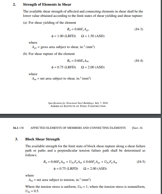
Roof diagram Image is a bit wonky as it was a photo of a screenshot, but hopefully it gives an idea

$\endgroup$
4
  • 1
    $\begingroup$ So a quick search: engineeringtoolbox.com/statics-t_63.html $\endgroup$
    – Solar Mike
    Commented Feb 3, 2022 at 9:51
  • 1
    $\begingroup$ note that most bolter connections are much stronger than the bolt shear strength because the friction between the bolted pieces carries much of the load. $\endgroup$
    – Tiger Guy
    Commented Feb 3, 2022 at 12:58
  • $\begingroup$ Little bit of additional info is that the column and beam are both 10mm thick. $\endgroup$
    – user36808
    Commented Feb 3, 2022 at 13:03
  • $\begingroup$ A vertical bracing gusset plate in addition would help counter any larger bending moments at the portal frame corner. The joint would be stronger than pure bolted connections. $\endgroup$
    – Narasimham
    Commented Mar 28 at 8:19

3 Answers 3

0
$\begingroup$

This a long comment.


The Bolt connection might not be the weak link

Bolt connections are usually considered as part of the overall structure and loading not in isolation. There are a lot of unspecified parameters in this problem, which affect the overall problem. I.e.

  • the I beam dimensions are not specified (only the thickness of the flanges).
  • the length of the horizontal beam is also not specified.
  • the length of the vertical columns is also not specified.

The reason those two are important is because 6xM16 Bolts are usually an overkill for most mundane applications. If they are connected on a 10mm flange of an I beam (which is unspecified), if the bolts are utilised anywhere near they maximum loads, then the flanges will most likely fold like paper.

So its very likely, that if you use those connection and you have a 10 meter horizontal beam, that the I-beam cannot support the loads while the 6xM16 bolt connection is barely feeling a thing.

Accordingly if the columns are 10 meters high, they might be prone to buckling, so further calculation need to be carried out.

One final unknown that can have an effect is the positioning/arrangement of the M16 bolts. I.e. if all of the bolts are vertically in a line then the top bolt will see different load to the bottom one in some cases. (And also if they are in a horizontal arrangement the loading will be more uniform).


Comments about bolts shear loading

The assumption that shear strength is about 60% of the tensile strength that refers to yield strength $\sigma_y$, not ultimate strength $\sigma_f$, so you need to be careful about that part. (This is a result of the failure theories like Tresca or Von Mises).

Additionally, about the shear, as Tiger Guy commented, the bolts most of the time are designed (IMHO they should be designed like that) transfer the force through friction. I.e. the bolts under tension produce normal compressive forces between flanges and the friction stops the movement).
$\endgroup$
6
  • $\begingroup$ Thank you. The columns are 3m high. The beam 4.8m long. The column I believe is 203 x 133 x 30kg UB. The beam 254x146x43kg. The bolts are in 2 vertical rows, 3 on each side. $\endgroup$
    – user36808
    Commented Feb 3, 2022 at 17:32
  • $\begingroup$ Thank you for the comments. In a nutshell, this is part of a roof support. At one side there is a load bearing wall... the room is 7m wide x 4.8m where the steel frame is(4.8m) with the beam and columns as described previously. It supports a timber framed roof structure of trusses at 600mm spacing, with a concrete tiled external roof surface. The wooden trusses are connected via dwangs/noggins. I guess I just want to know how much this bolted beam would support if I wanted to use the space above. I've tried to attach a brief diagram, but I'm not sure if that's possible. $\endgroup$
    – user36808
    Commented Feb 5, 2022 at 8:54
  • $\begingroup$ I couldn't find a diagram $\endgroup$
    – NMech
    Commented Feb 5, 2022 at 9:27
  • $\begingroup$ Yeah...I'm trying to figure out how to attach $\endgroup$
    – user36808
    Commented Feb 5, 2022 at 9:39
  • $\begingroup$ Sketch attached now $\endgroup$
    – user36808
    Commented Feb 5, 2022 at 11:33
0
$\begingroup$

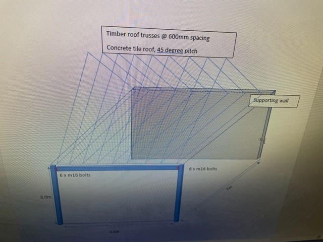
ANSI/AISC 360-16 Specs. pp. 195 has shear in Machin bolts at 60% of Fy.

It has solved examples too. And is free to download at, ANSI/ AISC

'

shear

EDIT

After OP's comments

  • If you are trying to find out how much your frame can support, starting from the beam it can very roughly support a uniformly distributed load of 3500kg/m meaning each end will receive only 7700kg.

  • Then you have to make sure the columns are laterally braced or supported against buckling and verify their load capacity.

  • The bolt groups under moment need to be calculated for rotation due to the torque as well as shear.

  • Foundation needs to be designed too.

  • More importantly, you have to know what will be the function of this frame, is it supporting any lateral loads like wind load, is it in a critical location?

  • Then we can apply appropriate load combinations and safety factors.

$\endgroup$
0
$\begingroup$

The information provided below is extracted from the AISC ASD Manual 9th ed. The metric specification and the corresponding grade is listed in the parentheses that immediately follow the US designations:

  • A307 (F-568 class 4.6) 3.1 kips/bolt

  • A325-N (F-568 class 8.8) 6.4 kips/bolt

  • A325-X (F-568 class 8.8) 9.2 kips/bolt

  • A490-N (F-568 class 10.9) 8.6 kips/bolt

  • A490-X (F-568 class 10.9) 12.3 kips/bolt

All values are the allowable load of 5/8" (M16) bolt with standard-sized hole (non-slotted nor oversized) and subjects to single shear.

  • N Bearing type connection with threads included in shear plane.

  • X Bearing type connection with threads excluded from shear plane.

Note, you need to make sure the connected metal part (web/flange) is adequate to carry the load without resulting in bearing failure.

$\endgroup$

Your Answer

By clicking “Post Your Answer”, you agree to our terms of service and acknowledge you have read our privacy policy.

Not the answer you're looking for? Browse other questions tagged or ask your own question.