4
$\begingroup$

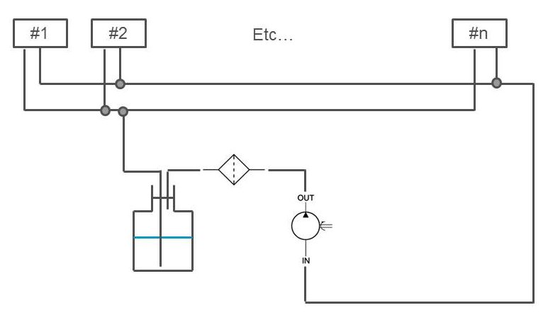
I have a liquid circuit which looks a bit like that:
enter image description here

The system is under suction, and the flow rate through each unit should be about 10ml/min. However, we noticed that unit n and the ones the furthest away from the pump and bottle were not getting enough flow. Any suggestions on how to make sure each unit gets about the same amount of flow? My initial thought was to add a second pump at the end of the line to help the liquid (water) go round the circuit. Another possibility is to separate the load of n units into 2 circuits in parallel, 1 to n/2 and n/2 + 1 to n at the bottle/pump location so that both circuits will have a better chance of seeing the same amount of liquid.

Some precisions:

  • there is a restrictor on the return path of each unit to restrict the flow and create a pressure differential to allow the liquid to go round
  • the length from unit #1 to unit #n is about 3m, the pump and bottle are located between unit #4 and #5.
  • the tubing diameter along that length is 4.8mm ID, and each teed off line in each unit is 1.6mm ID, with the restrictor 0.38mm ID (~60mm length)
  • the pump is a diaphragm liquid pump
  • there is a vent port with a filter on the bottle lid to allow for the pressure to vent out.
$\endgroup$
1
  • $\begingroup$ Totally not my domain but looks like converting from bus architecture to star architecture would help :) $\endgroup$
    – SF.
    Commented Feb 5, 2015 at 11:34

2 Answers 2

5
$\begingroup$

Looks like a typical water based central heating system (apart from the scale).

You need to balance the flow by restricting flow for the units that get too much.

This can be done by partially closing a valve or adding a restrictor for those units. Better if there is some kind of feedback loop to auto restrict when too much water is going through.

$\endgroup$
1
  • $\begingroup$ Thanks, as I mentioned there is a restrictor on the outlet of each unit, but it is the same for each one. Having a "customised" restrictor for each unit is not really feasible in practice, although some kind of check valve might work if not too expensive. I'll look into it. There is a flowmeter in the system at the outlet of the filter (which is actually on the outlet, not the inlet, of the bottle), but that doesn't tell us the flow in each unit, and the system being under suction, we can't measure it easily. $\endgroup$
    – am304
    Commented Feb 5, 2015 at 11:40
1
$\begingroup$

Looks like you want a typical register, so that sum of the pipe length supply and return is the same for each unit. No guarantee that it works, though. I'll see if I make a drawing if the idea is unclear.

$\endgroup$
2
  • $\begingroup$ Thanks. Unfortunately, if I understand correctly, this is not feasible. The units the furthest away from the pump & bottle will have the longest length of pipe, both on the supply and return sides. $\endgroup$
    – am304
    Commented Feb 6, 2015 at 11:07
  • $\begingroup$ hydraulicspneumatics.com/other-technologies/… see here for ideas. There'S also flow dividers where you mount several pd pumps (like gear pumps) on one shaft so they are forced to transport the same flow, I'll edit this into the question body when ther's time. $\endgroup$
    – mart
    Commented Feb 6, 2015 at 13:57

Your Answer

By clicking “Post Your Answer”, you agree to our terms of service and acknowledge you have read our privacy policy.

Not the answer you're looking for? Browse other questions tagged or ask your own question.