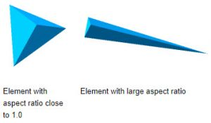
One important (and often neglected) parameter in FEM meshes is the aspect ratio. The aspect ratio is the measure of a mesh element's deviation from having all sides of equal length. A high aspect ratio occurs with long, thin elements.

figure: low and high aspect ratio (source Soidworks blogs)
Because having high values of aspect ratio means that the FEA accuracy reduces, therefore most mesh generators try to make -as much as possible- low aspect ratio elements.
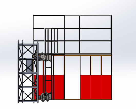
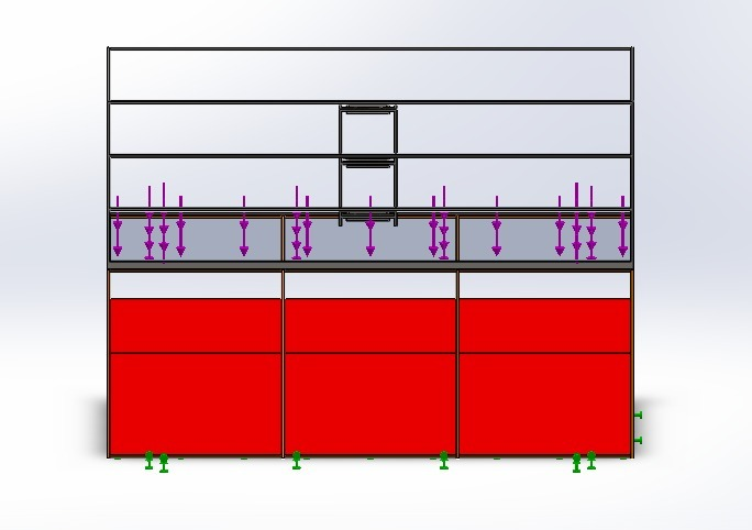
The problem occurs with rods and sheets of metal. Both of them have (at least) one dimension that is significantly higher that the other. So for example for an element representing a sheet (there are a lot like that in the structure you are presenting), the through thickness of the shell imposes a minimum length for solid elements.This does the following:
- increases the aspect ratio,
- uses only one (or two in the best case) elements in the direction of the thickness.
Although the mesh generator will try to create a mesh with finer solid elements, there are practical problems. To explain it the following example is usually used.
Assume you want to model a solid cube with an edge 100 mm. Also for simplicity assume you will use cubic elements (not the basic tetrahedral). Then you can use
- 1 cubic element, with edge equal to 100mm
- 8 cubic elements with and edge equal to 50mm
- 64 cubic elements with and edge equal to 25mm
- 512 cubic elements with and edge equal to 12.5mm
- ...
if you wanted to model with 1mm elements you'd need 1000000 elements.
So when you reduce the element size, the computational effort increases by a lot (and the memory requirements).
In your case, because you have a lot of sheets elements and gears with teeth (which I would remove for the purposes of the analysis)., the mesh generator tries its best for a good compromise.
The solution as jooja pointed is to use shell and beam elements where appropriate. This is still something that needs to be carefully implemented (and there are a lot of do's and don'ts but that's another matter).


