1
$\begingroup$

I have been doing some experiments using a small brushed permanent magnet DC motor as a generator. I have it coupled to a similar (as in, exactly the same) motor which is powered by a PSU. thus driving the 'generator'. Note, this may look like a homework like question, but it's actually first steps in an actual real application.

In more detail, both motors are 12V, Current: 0.18A, Power Rating: 5.662W, Rotational Speed Max: 8,768rpm, Efficiency: 59.58%, Direction of Rotation: Anti-Clockwise

https://ie.farnell.com/velleman-sa/mot3n/dc-motor-12vdc-180ma-11500rpm/dp/3498470?CMP=i-bf9f-00001000

Firstly, some questions relating to this motor, used as a motor.

Consumption: From looking at many similar sized motors while choosing this one, I came to the conclusion that the power rating in watts, seem to be the mechanical power output (putting the RPM and torque into a calculator site gives 5.69W). If 100% efficient it should thus consume 5.6W, as it's max 60% efficient it should really consume ~10W. Yet, the specs say 12V * 0.18a = 2.1W. What am I not understanding?

Also, the current consumption is indicated at about 1A by the PSU meter.

Direction: The spec lists a direction for the motor. I thought DC motors went just as well in either direction (e.g. car window up/down). I took one of them apart expecting the brushes to be angled etc but looks the same in both directions to me. Why is a direction given, and what are the implications for generation (more on this later)

Generation questions

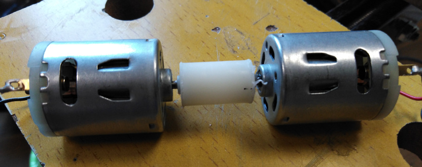
Setup: the two motors are joined using a coupler, see pic. The driving motor is supplied 12V from the PSU and the generating motor is connected to some resistors to form a load (I'll just detail one value, but I tried 5/10/10/20 ohms)

Results: With a 10 ohm load (9.8 actually) I measure 5.8V = 0.59A * 5.8V = 3.4W. This seems perfect as the driving motor should be putting in 5.6W (mechanical), * by the 59.58% efficiency = 3.3W (electric), which is what I'm getting

This simple view assumes I'm getting a nice flat DC waveform out, but I assume it's really like AC straight from a bridge rectifier (don't have a scope) so maybe RMS should come in somewhere?

Input power: My main question, and getting back to the driving motor, is the readings I'm getting on the PSU/driving motor side. The PSU has a switchable meter reading volts or amps.

With the above test load, the driving motor is consuming about 1.2A at 12V, according to the PSU. However, using my multimeter, I read about 7v and 0.5 to 1.5A (all readings are jumping about wildly - RFI on cheap meter?) So, according to the PSU the driving motor is consuming 14W and 3.5 to 10W using the multimeter - both way more them the 12v* 0.18a = 2.1W specs. IS back EMF affecting my readings?

Finally, another oddity. When reading the voltage across the load resistance, I saw that for some I got a stable reading while for others the meter digits were making no sense. But, if I reversed the driving motor supply polarity, the readings stabilized.

enter image description here

EDIT 23 Sept '21

After spending time trying to get good readings with two multimeters, I bit the bullet and ordered a cheap PC based oscilloscope. So I'd like to update the question with these results

Setup

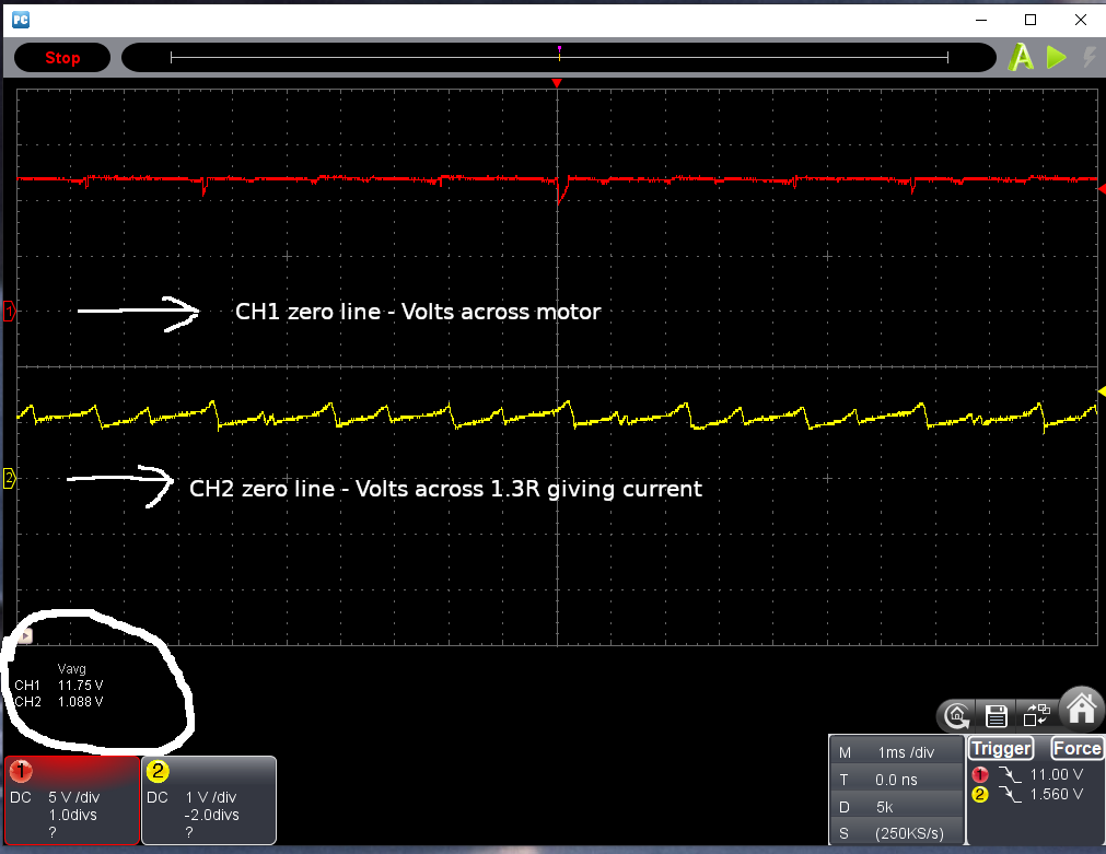
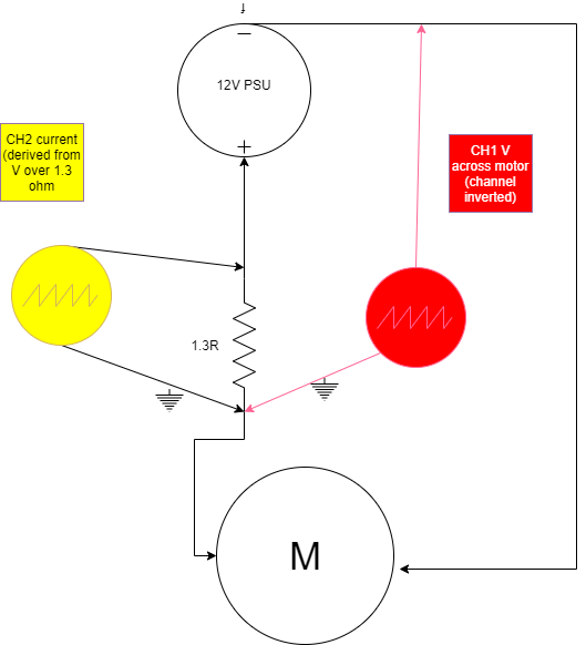
On the drive side I used Channel 1 to measure voltage at the motor, and CH2 to measure voltage across a 1.3R resistor (and thus calculate current via Ohm's Law). As the two probe grounds are connected, I had to use the motor/resistor junction as common GND for both channels and invert as required

enter image description here

Results on driving side

I'm seeing an average of 11.75V across the motor and 1.0V across the resistor (=0.77A) giving a power in of 9W. The motor efficiency is 60% so this should give 5.4W mechanical output, which matches the rating of 5.662W

enter image description here

Output

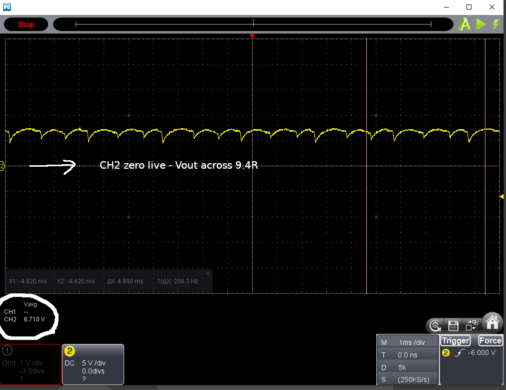
Not shown in the setup diagram is the fact the motor is coupled to another one as before with a 9.4R load. Output average is 6.7V giving 0.71A and thus 4.7W. Assuming the input side is correct, this means the motor is 87% efficient as a generator. Have I made a mistake somwhere?
enter image description here

$\endgroup$
1
  • $\begingroup$ Can you add a capacitor, to the motors? I would go from as low as 0.1uF to high as 100uF, just to see if the ripples get filtered. $\endgroup$
    – jay
    Commented Aug 30, 2021 at 21:11

1 Answer 1

2
$\begingroup$

Power rating of a motor is the mechanical power out. Divide that by efficiency and you should roughly get electrical power in. Efficiency will be different if not at full-load. To get 6W mechanical @ 60% efficiency, you have to put 10W electrical in.

You have a problem. Driving motor correctly means generator is going in the incorrect direction, which may explain But, if I reversed the driving motor supply polarity, the readings stabilized. Small, cheap, dc motors can have brushes aligned to get more torque in one direction.

This simple view assumes I'm getting a nice flat DC waveform out, but I assume it's really like AC straight from a bridge rectifier (don't have a scope) so maybe RMS should come in somewhere?

Nope. You have a commutator, which the brushes ride on. You'd get DC with a ripple. You could add an inductor in series with output to filter ripple.

On your varying power consumption. What size wires and how far is power supply from motor? Your efficiency has to be applied to motor and generator. There is also a mechanical efficiency between the motor and generator. 10W means 6W (60%) from motor and 3.6W (60%) from generator.

Here you also have a problem. If your generator is at full-load, your motor will be overloaded. I suggest you graph out input and output (measure voltage and current at different loads).


Most motors (DC and three-phase ac) can be used as generators with some being better than others.

Efficiency has to deal with losses (copper loss, hysterisis, windage, bearings), so they apply to motor or generator. Although the motor will be at 60%, generator will be different, probably slightly higher because copper losses will be less (half-load means half current so I2R losses will be 25% of full-load copper losses). You have a small motor, but theory still applies.

Your erratic readings are due to motor going in the wrong direction. As proof of concept, you have a genset.

If you drive a BLDC, you can get a three-phase generator.

$\endgroup$
6
  • $\begingroup$ Thank you. I think I understand the efficacy side of things, and you confirmed it. Also that a motor can be used as a generator, and I should expect the same efficiency (in reverse, as in elect pwr out < mech pwr in),yes? $\endgroup$
    – KevInSol
    Commented Aug 31, 2021 at 16:11
  • $\begingroup$ i seem to be getting a more stable output when running the generator motor in reverse... i will try to rig things so they both go in the same direction. The supply wires are pretty thin (no idea of guage - just small signal wires, 60 cm) so I doubled up o them and thus twice the gauge and half the length (30cm). No change noted. $\endgroup$
    – KevInSol
    Commented Aug 31, 2021 at 16:20
  • $\begingroup$ Try to measure voltage across one wire. Double it for total feeder loss. $\endgroup$ Commented Aug 31, 2021 at 16:22
  • $\begingroup$ What concerns me most at this point is the very erratic readings (V and I) at the driivig motor side. not having any inductors (and I think you were talking about output anyway), I placed a 10 micro farad cap across the driving motor. still impossible to measure the V / I drain. ad why do the specs suggest it should consume ~2w? $\endgroup$
    – KevInSol
    Commented Aug 31, 2021 at 16:24
  • $\begingroup$ 10W means 6W out and 4W to motor. $\endgroup$ Commented Aug 31, 2021 at 16:26

Your Answer

By clicking “Post Your Answer”, you agree to our terms of service and acknowledge you have read our privacy policy.

Not the answer you're looking for? Browse other questions tagged or ask your own question.