4
$\begingroup$

My team is trying to build a mechanical cannon for a final project for a course and we are running into some problems with our motor stalling.

Our motor stalls when the plate hits either side of this railing (as shown with circles below) because, I think, it creates infinite tension that the motor can’t overcome. Once our DC motor is fully stalled and refuses to move in the direction of infinite tension, we try to move the motor in the opposite direction to free it up, but it stays stuck. We need to physically intervene to “unjam” the motor. Sometimes we can also press our button to move the motor backwards quickly and consecutively and it will unwind.

We don’t want to use a limit switch since we have to stay within a “required budget”, so we are wondering if there would be any other way to prevent this motor from becoming jammed. We were thinking that the jamming of the motor occurs because there is too high of a current draw when it stalls, so a solution would be to put a resistor in series with the motor driver + DC motor interface to reduce the amount of current that is drawn when the motor stalls. We have no idea if this is a robust solution that would allow the motor to easily unjam. Any ideas would be really appreciated !

Some specs for context:

DC motor that moves plate:

DC Motor Threaded Output Shaft Lead Screw 6V Motor Stepper Lead Screw Actuator Gear Motor with Long M355MM Lead Screw Thread Output Shaft

Motor has a 6V rating and a stall current of 1A
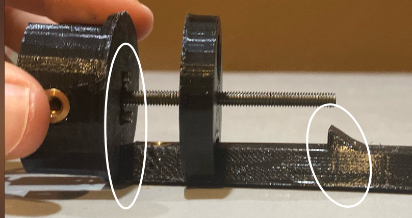
enter image description here

$\endgroup$

5 Answers 5

2
$\begingroup$

When you bump the plate on a thread off the edge, the plate tilts, inertia of the motor drives the plate to a larger angle. Deformed plastic grips much stronger than what motor can move. To avoid this you need to reduce this bending of the plate due to inertia.

  1. You could make a plate thicker. It will bend less. It will capture the motor's shaft less when it is bumped off the side. Thats the real problem.
  2. You could glue a piece of thick cloth on plate's bumping areas, to make the bump longer in time. This way inertia of the motor will be dissipated by the cloth, and motor will be pushing into with the same force as it will be pulling out of it. And will more often be able to get out.
$\endgroup$
2
  • $\begingroup$ I agree with the first part of your answer, but I don't think the inertia is significant; consequently I don't believe the cloth will do anything. $\endgroup$
    – Drew
    Commented Dec 22, 2020 at 7:10
  • $\begingroup$ If inertia would not be significant, and motor's momentum (force-leverage) is similar at max speed and at low speed, then motor would equally be able to be stuck and unstuck, or will slightly prefer to unstuck because bent plate is pushing away. Motor does prefer to get stuck. Meaning something makes it easier to tighten the screw than un-tighten. Its either a momentum at higher speed is larger, which is unlikely for small motors that usually use magnet, or its inertia. I agree with your explanation, I just want to add that something makes the stuck\unstuck directions being not equal. Chances. $\endgroup$ Commented Dec 22, 2020 at 8:20
3
$\begingroup$

Considering that this is a class project, depending on what you use to control the DC motor, you might be able to use current limiting. The technique is called current sensing.

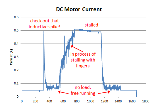
When a DC motor is running freely then it draws much less current than when its about to stall (see image below)

enter image description here

When the current stars to increase that is a signal that the DC motor is about to jam. So what you can do then is stop it.

Most Arduino's have an option for current sensing. The main problems are that:

  • it uses a analog port. The analog ports are quite slow, and they are not that many.
  • There are some False Positives that you have to account for (i.e. transient peaks of current usually when starting and stopping the motor).
  • you will probably need to do quite a bit of work for to tailor it to your DC motor. (However that is among the educational points of the project you are doing. )

Have a look at the following blog for more details

$\endgroup$
1
  • 1
    $\begingroup$ That spike isn't an inductive spike, that's the stall current (maximum torque) being applied as the motor gets up to speed. $\endgroup$ Commented Dec 11, 2020 at 19:45
1
$\begingroup$

I think it's the effect of "tightening the screw", a lot of friction distributed over a large area. Even if the plate doesn't bend, it will still accumulate a bunch of tension, and as a result, friction. You need to stop the motor before that happens.

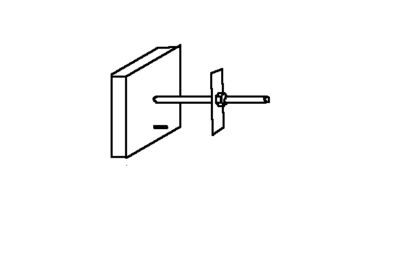
I think a mechanical stop could work: put a small "blade" of sheet metal on the shaft (squeeze it between two nuts to fix it in place) and a nail or other small bar / protrusion / obstacle on the moving plate. Angle the "blade" slightly, like a propeller, so that during the motion of the plate outwards, its leading edge will catch against the nail and stop any further rotation dead, but on motion in the opposite direction, will slide over the nail, at worst flexing slightly.

enter image description here

$\endgroup$
0
$\begingroup$

I'd make both stops as big as the moving plate itself, so you're not putting a moment on that plate. I imagine that's mostly what's causing the problem. You could also use springs or rubber bumpers at the ends so it's not so much of a hard stop, but it will compress until it just reaches stall torque. That might help prevent it from really getting stuck from the momentum hitting a solid end stop.

$\endgroup$
0
$\begingroup$

What's causing the plate to become stuck is a binding action. As the plate hits the hook stop, it will start to tilt. As it tilts further and further the friction between the disk and screw will increase until the motor stalls. As you've noticed this friction is basically omnidirectional, so once the motor is stalled you generally cannot retract it.

This action will be less severe when the plate hits the flat face, but it can still happen, the threaded interface between the plate and the screw will tighten down just like tightening a fastener.

To fix this, first of all make the hook side symmetrical (hooks on top and bottom) so that the plate will not tilt sideways.

From there it gets harder. Because of the fine pitch of the screw, I'm not sure this mechanism will ever be 100% reliable without limit switches. The fine screw gives it strong tightening action when it crashes at the end of the stroke.

Reducing flexture in the assembly might help. Basically you want it to hit the limit and stop dead, you don't want any part of the assmembly to compress or bow as that will act as a spring applying friction on the return stroke.

I don't think weakening the motor will do much good, since the loosening force will be reduced along with the tightening force. A better bet would be to configure the motor so that it produces a burst of greater torque at startup. You may, for example be able to use a resistor and large cap in parallel. When the motor starts, current flows through the cap giving the motor the full voltage; once the cap is charged the current must flow through the resistor, causing a voltage drop. That's just spitballing, but it might work.

You could also change some of the materials to reduce friction. For example you could use a brass threaded insert in the plate. You could also add lubricant.

$\endgroup$

Your Answer

By clicking “Post Your Answer”, you agree to our terms of service and acknowledge you have read our privacy policy.

Not the answer you're looking for? Browse other questions tagged or ask your own question.