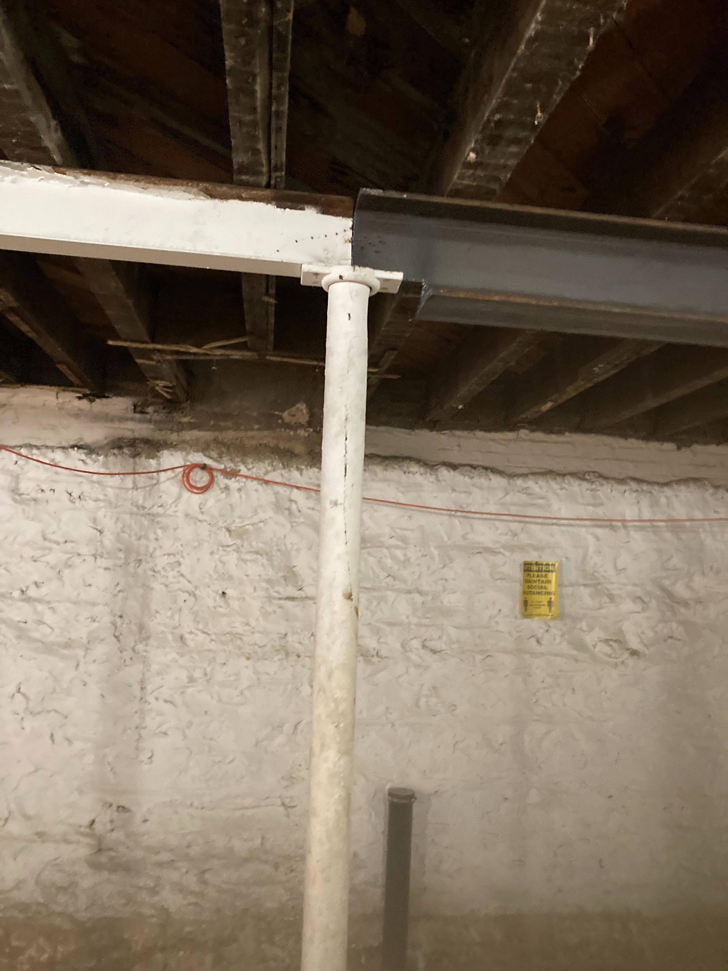
I'd like to confirm whether the replaced beam in the attached picture is structurally sound given the end was cut to a T instead of an I. I had a qualified structural engineer approve the work but I'm curious about the engineering properties of the final result.
-
5$\begingroup$ How did the structural engineer arrive at their approval? $\endgroup$– martCommented Sep 30, 2020 at 14:27
-
9$\begingroup$ In what way are the beams fixed to the vertical support? There's no connection apparent between the beams, is there one? $\endgroup$– martCommented Sep 30, 2020 at 15:13
-
1$\begingroup$ Also while your at it (are you at it?) provide a sketch of the complete system, as can be seen in the many answers it kinda matters where else the beams are supported. $\endgroup$– martCommented Oct 1, 2020 at 9:21
-
3$\begingroup$ This is not my discipline, but I have a horrid feeling that I live in the same country. It looks suspiciously as though there is pinning at the end of the old beam which is omitted on the new one. What are those features that look like cracks in the web of the old beam, and along the length of the column? $\endgroup$– Mark Morgan LloydCommented Oct 1, 2020 at 10:03
-
$\begingroup$ "Qualified" in what way? They've heard of structural engineering? $\endgroup$– Asteroids With WingsCommented Oct 2, 2020 at 18:56
7 Answers
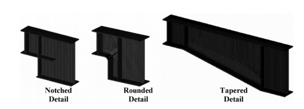
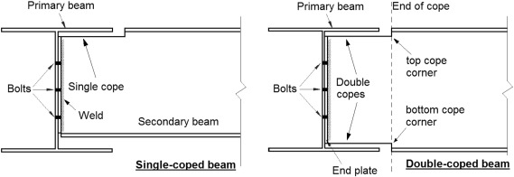
While not an ideal situation, it is common enough that this type of cut/reduction of the beam as it comes to its support actually has a name. This is more often referred to as a coped or dapped steel I beam. There are various ways to transition from the full depth of the beam to the depth you may require at your support. Some examples are:
Sometimes the top flange (wide thin plate at top and bottom of beam) will also be cut back to permit connections to the sides of other beams and avoid interference with their flanges.
At your connection, the moment your beam is required to support in this case is essentially 0. The moment is resisted primarily by the flanges that is why it is not that big of a deal to trim them back at the end of the beam in a simply supported case (ie not continuous with the next beam, or rigid connection to the support). I am assuming the span for the beam on the right is either much longer than the beam on the left, has a higher loading on it, or requires less deflection. Those would be some of the main criteria for using a deeper section.
The force you usually need to worry about at your column is shear. Shear is primarily carried by the web (tall thin vertical part of the beam). In your setup, Shear is greatest at the support. IF the loading conditions of the beam on the right is very similar or less than the beam on the left, you should be ok for the shear capacity in the web, because (assumption) the web of the beam on the left is about the same size as what is remaining on your beam on the right.
Now depending on the loading conditions, your beam may be absolutely fine the way it is. And after rereading your question, apparently it is just fine as an engineer signed off on it. It is just not common to see it without a few more pieces that are missing. These missing pieces would stress a few engineers to some degree without knowing the full loading conditions which your local engineer had access to.
If you compare your beam end detail to the detail in the first picture example you should notice a couple of things. First and foremost, there does not appear to be a flange welded on to the bottom of the cut web. This is done to help reduce the contact pressure of the web on the supporting material that it will rest on. You will often hear this piece of steal referred to a bearing plate or shoe. Shoe and bearing plate, and bottom flanges are typically anchored to their support in some fashion that keeps them from sliding out of place. It cannot be seen from the angle of your photo, but I am really hoping that the web of the beam on the right is welded to that thick steel plate at the top of your column. This help will keep it from slipping off.
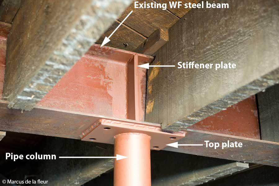
The other thing you will note is a vertical stiffener plate (see picture below) in the example but not in your photo. While they are not always required (depends on code and loading conditions) it is quite common to find them at bearing support conditions at end of beams, under point loads, and around/adjacent to cut outs. There are other reasons for them too but not going into that detail. The job of the stiffener in this case would be to ad stability to the web and keep it from buckling.
I once evaluated a bridge in a different region than me. My calculations showed the beam as being fine for shear and moment. A local engineer pointed out that there were no stiffener plates at the supports. In my region the beams are usually made up from welded plate that have been suitably sized for the required thickness and do not require these support stiffeners. I went into the code and did the check and it turned out the web without a stiffener plate was 50% undersized. I thought this was crazy that a bridge could have been around for so long without serious issues and be 50% undersized. I wound up going back about 4 versions of the bridge code, and between version 5 and version 4, the formula for calculating capacity changed and a 2 was added to the formula. So the bridge was fine when originally designed, but due to changes in the code, it now required support stiffeners. Thankfully a relatively easy fix.
That story mainly to tell you that an engineer with knowledge of local conditions and codes can be very helpful in keeping you out of trouble. You did the right thing by having a local structural engineer review the connection.
There is nothing wrong with dapping or coping a beam as long as the coping/dapping has been properly design to deal with the loading conditions it will be expected to face.
UPDATE
Just stumbled on this photo while I was closing out my various google searches for images. It shows the type of connection people would ideally like to see. Note the copped wood timbers so the can fit inside the support steel I beam too! looks like they welded the top plate instead of bolting the beams to it.
-
$\begingroup$ I admit, I'm not a structural engineer. (graduated with a CivE degree, but went into another field). But whaat you've said matches up with everything I learned in school -- so long as you don't try to bond the beams together like kamran recommended, your primary issue is going to be sheer at the ends, not moment. I'd actually be more concerned with the possibility loss of lateral strength (buckling or slipping off if there was an earthquake, car crash, or other sudden lateral force $\endgroup$– JoeCommented Oct 2, 2020 at 15:54
-
$\begingroup$ @Joe your later concerns are exactly why I mentioned that I hoped the web was welded to the top plate of the column. I actually would prefer bolted but that would required more steel that is not there. Welding changes the support condition from pinned to fixed. But again, you need to know what the loading condition are to better assess. Also are you going to the golden Cadillac of solutions, or just what you need to get by? $\endgroup$ Commented Oct 2, 2020 at 16:47
-
$\begingroup$ But wouldn't welding it to the plate mean it's no longer simply supported? I'd be afraid of transferring a moment to the column if there were unequal loading on the two beams. If might be safer to weld or bolt on a couple of sections of L-angle to make a new flange / foot that just rests upon the column. (but I'm not a structural engineer, so don't know if there are other implications to doing that). $\endgroup$– JoeCommented Oct 2, 2020 at 17:22
-
2$\begingroup$ @Joe Correct. The addition of a couple of angle to form a shoe/flange/bearing plate and then bolting the bearing plate to the top plate of the column is the ideal way to go if you need to preserve a true pin connection. The plate should also have slotted connections. However, for relative light loading the addition of moment to the top of the column may not be significant. I tend to deal with bridge pier column that are meters in diameter as opposed to basement jack post style columns, so I am not sure off the top of my head how much bending/eccentric loading they can handle. $\endgroup$ Commented Oct 2, 2020 at 18:08
This is a textbook example of what not to do.
We don't get into stress concentration at the cut off of the corner of the beam, or the fact that the two very different stiffnesses of the beams are a constant cause of differential deflection and vibration.
The thin edge of the web sitting on the column cap is an unstable mechanism waiting to either kick the CC out from under it or rotating over it and causing the column cap to be pressured off from under the joint. Especially since there is no continuity between the new and old beam webs and flanges.
I would recommend:
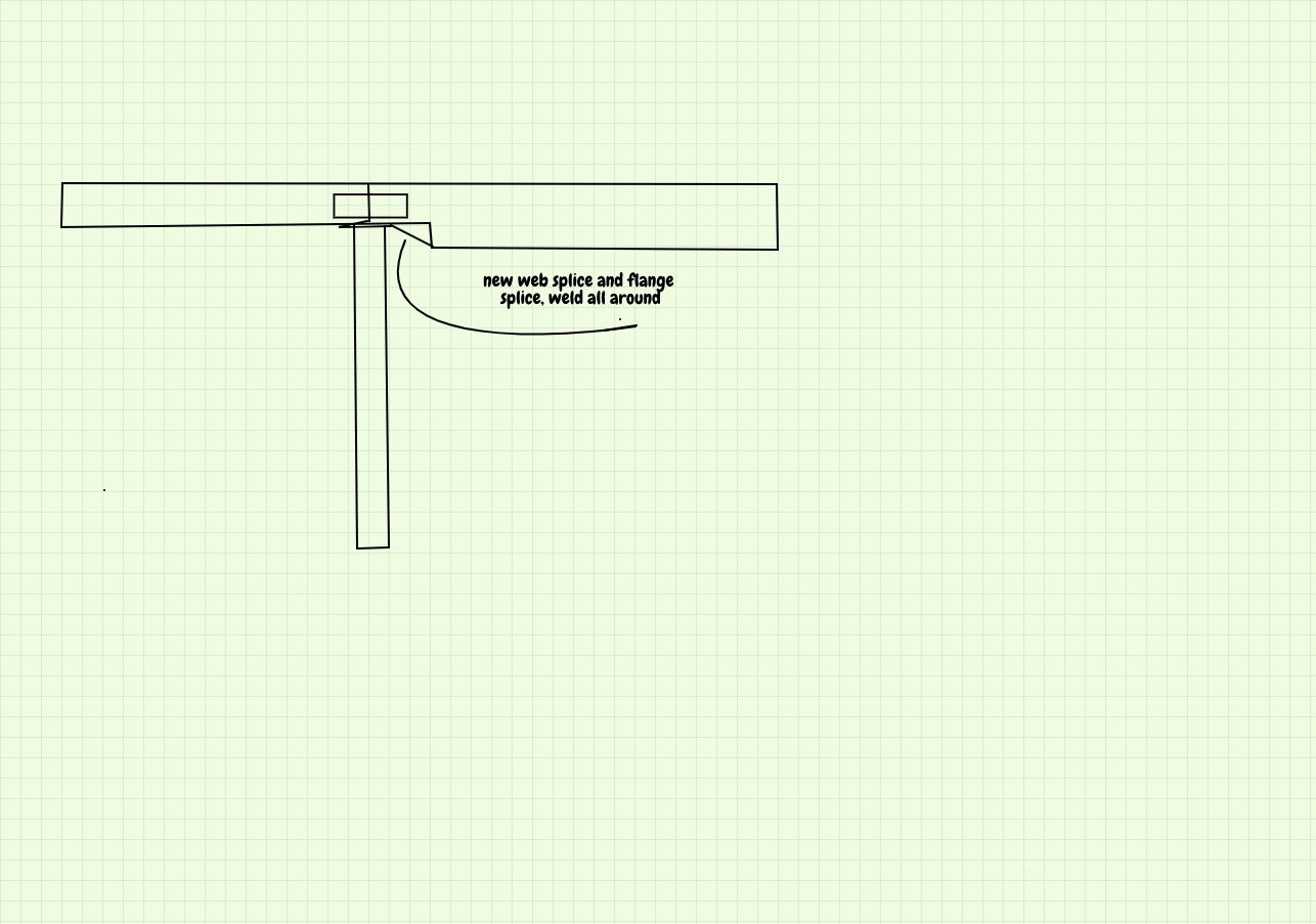
Add a triangular splice at the bottom of the cut web to it and add to the lower flange an extension all the way to the CC with continuous weld all around.
Add a 4-inch by 12-inch splice connecting the two beams on the web joint.
Weld the flanges together.
-
14$\begingroup$ If the guy who did the first job also does the welding, he will probably set fire to the wood beams and/or burn a hole in the floor above! Or start by removing the support post completely to get better access to do the welding. There is no limit to human stupidity. $\endgroup$ Commented Oct 1, 2020 at 0:31
-
4$\begingroup$ @alephzero, right, probably. They need to use an experienced welder and cover around the work area with wet blankets. Also, weld intermittently with a pause in between. I admire the OP's sharing his concern. I could imagine how many empty cans of bear where left around after. $\endgroup$– kamranCommented Oct 1, 2020 at 1:23
-
6$\begingroup$ @kamran It's much more convenient to buy bear in cans, instead of having to go out and shoot it and skin it yourself. (Some typos are irresistable - sorry, not sorry! ;) $\endgroup$– GrahamCommented Oct 1, 2020 at 9:58
-
$\begingroup$ @Graham, hehe, phone spellchecker. $\endgroup$– kamranCommented Oct 1, 2020 at 12:12
-
1$\begingroup$ While it's not necesarily achieving maximum utilisation from the material, it's not necesarily wrong. Plenty of steel connections don't run the flanges to the very end of the web (see other answer). You also seem to have neglected the fact that the old beam is apparently cast iron. Sure, you could detail it differently and get more strength from the beam, but does the client want a design that's strong enough and safe enough or a design that's three times as expensive to implement? There's no evidence that the detail as implemented is unsafe. $\endgroup$– achrnCommented Oct 3, 2020 at 9:45
If the white beam on the left is adequate, the one on the right is much bigger than it needs to be, so hacking a piece out of it might not matter.
In general this idea is a horrible example of engineering "design".
Still, if you follow the sticker on the wall and "maintain social distancing," that will reduce the number of deaths when it fails :)
-
2$\begingroup$ What if the white beams span is much shorter then the one of the right? What if the white beam is only support a bunch of office spaces and the new beam on the right is where they are planning on stock pilling pallets of bricks prior to shipping? Equal span/loading conditions I say sure probably fine as his engineering agreed with. Lots of stuff not shown in the photo that may explain the change in beam depth. $\endgroup$ Commented Oct 1, 2020 at 3:06
-
1$\begingroup$ Loved your social distancing comment though! $\endgroup$ Commented Oct 1, 2020 at 3:07
-
$\begingroup$ Based on the overall design of the poll, the white beam continued across the top. I wonder if it failed/rusted and needed replacing, or if some other change (out of shot) forced a change. $\endgroup$– CriggieCommented Oct 2, 2020 at 1:45
TL;DR: Since we can't see how the beam is supported on the other end, its not clear whether its structurally safe. Still, I don't believe this configuration can transfer safely any substantial structural load..
When I first saw the image, my first thought was that this is the one end of a simply supported beam. I thought is was an accident waiting to happen. Some of the things I don't like that pop to mind:
- The two beams (of the column for that matter) do not seem connected in any way.
- the web resting on the column is unstable.
- the web is now more susceptible prone to buckling instability. (it reminds me of trying to balance a pencil on its tip).
- The reduction in second moment of area will be high (probably not important).
- the contact stresses will be high (depending on the load that the beam carries)
If it is still standing, I am guessing there might be the following:
- only because there beam does not carry any load.
- the way the beam is supported on the portion of the image we can't see. I expect that it probably is an overhang simply supported beam. Like the following image.
The part that we see in the question photo is the red rectangle. So the beam might be adequately supported from the other side. If that's the case then this end doesn't transfer any substantial loads.
However, I honestly don't see, how this arrangement can carry any substantial structural load.
-
$\begingroup$ do you mean if the part we see in the OPs picture corresponds to the right support in your image, so the upper flange of the beam is in tension? $\endgroup$– martCommented Sep 30, 2020 at 14:22
-
$\begingroup$ No. I mean that if what we are seeing is the leftmost part of the structure beyond the left support. Basically a left overhang simply supported beam. I will edit this when i get baxk home. $\endgroup$– NMechCommented Sep 30, 2020 at 14:50
The lower flanges resists a downward bending force that puts tensile stress on the lower flanges. Removing a short section of the lower flange lowers its bending strength but because of the very short lever arm at the cut , bending stresses are relatively very low ; So a clever solution. The shear strength is also reduced but from the visual sizes ,the black beam is substantially stronger ,so a non-issue. I have used this same technique with wood when there is a space problem.
I am not a structural engineer, but this whole setup seems like an accident waiting to happen:
- Steel is far stronger than wood, therefore logic would dictate that a new steel beam of the same strength would be the same size or smaller than the wooden beam it is replacing - yet it is actually far larger, necessitating the cut to make it fit.
- I-beams are absolutely not meant to be cut in this manner - their very structure is designed for optimal load-bearing capability. This cut not only decreases the load-bearing capability of the beam, but also does so at a location where the beam is going to experience high stress. The end result is that the beam is significantly weakened.
- Steel is far heavier than wood, yet there has apparently been no provision made for reinforcing or replacing the support column(s) of the new beam.
- There is nothing joining the old and new beams to each other, or to the support column. The only thing preventing this whole shebang from coming apart is the weight of the wood above pressing down and keeping everything in place. Natural expansion and contraction of the beams and support column could easily, over time, lead to one or both of the beam ends shifting off the top of the support column - with likely disastrous consequences.
In short, I would strongly recommend getting a second opinion from a different structural engineer. What you've been sold seems incredibly unsafe.
Several comments above have suggested that the white and steel beams be welded together, however it looks to me like the white beam is wood! Even a gusset plate would be difficult, though not impossible, due to the great difference in width.
Regarding the cut steel beam, I would be suspicious of it unless the beam was way oversized. There is nothing at the bottom to stabilize the vertical web of the beam; with a heavy enough load it could buckle. Even a slight sideways bend (no longer resisted by the missing bottom web) could cascade as more and more load falls on the still-vertical portion of the vertical web. All in all, a thumbs down from me unless a replacement bottom web had been welded in (and connected to the remaining bottom web).
