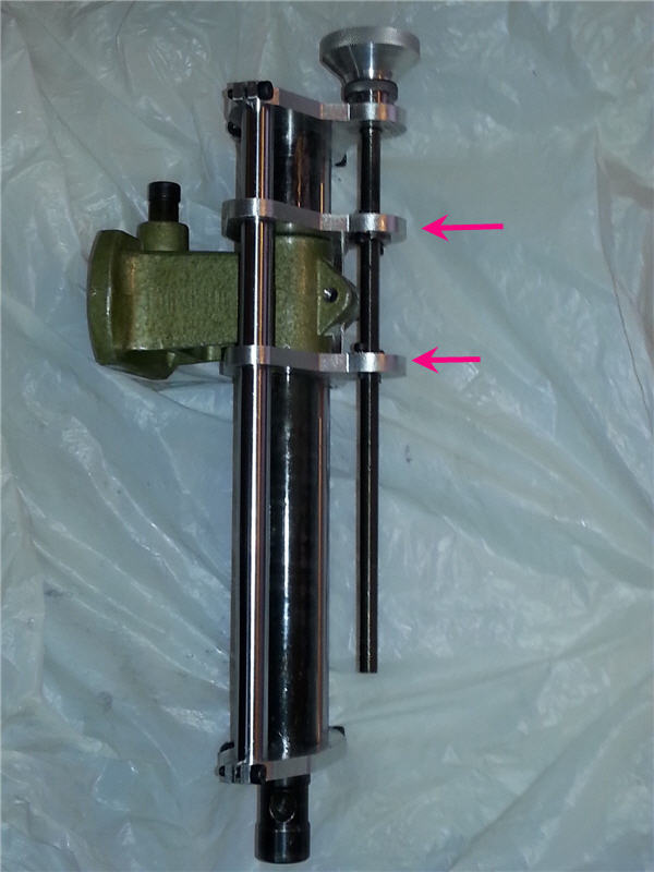
It's difficult to determine from the photo which parts are moving and which parts are dependent on another part for specific movement. If you get proportionately smaller travel per revolution of the main knob, the other parts of the assembly could be a differential screw mechanism.
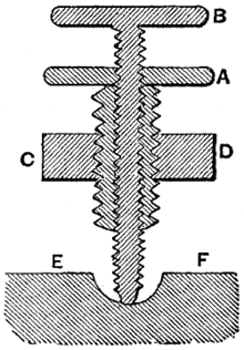
Differential screw mechanisms are used in micrometers, in which the main knob rotates a substantial amount and the spindle moves a fraction of the distance. It is a construction in which an inner rod is threaded to one specification and the outer rod is threaded to a slightly larger or smaller specification.
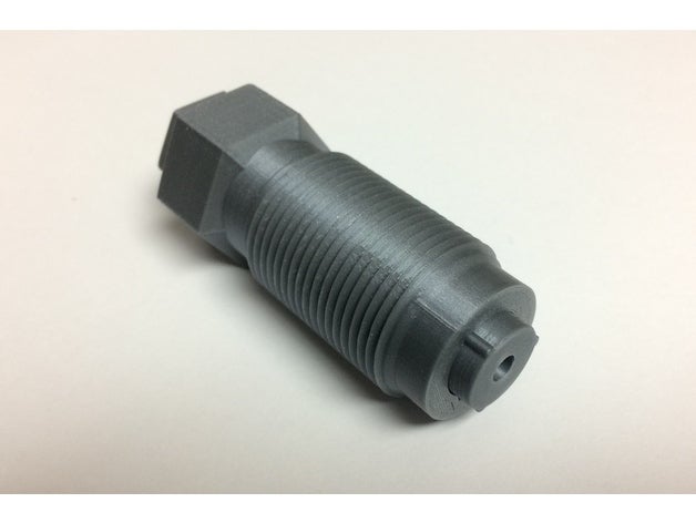
I've constructed a 3D model in which the travel of the spindle is 0.25 millimeters for each rotation of the main knob, which is threaded to 1.0 mm pitch, while the inner thread is 1.25, a difference of 0.25.
The reason for such a mechanism is that it is easier to build a 1.0 mm and a 1.25 mm pitch thread compared to a 0.25 mm pitch, which is what would be required if one desired to bypass the differential threading option.

Thingiverse provided me the model to learn more of this construction.

The outer threads of this mechanism would be engaging the brackets you've noted in the photo. Note also the key and matching keyway between the inner threaded rod and outer sleeve. It's critical that the portion does not rotate in order to provide the fractional movement desired.
In your photo, it's logical to expect that only one of the brackets contains a differential mechanism, while the other provides an alignment bushing of sorts.


