1
$\begingroup$

While gain margin(s) and phase margin(s) in Bode Plots of open loop transfer functions are defined at particular frequencies (when they exist) --- such as phase margin is defined at frequencies where the dB gain cuts through 0 dB ------ may I ask if these particular frequencies (ie. gain margin frequencies and phase margin frequencies) are points of interest only because we can conveniently define them at these frequencies?

I was thinking that, if we choose a particular frequency in a Bode Plot where the dB gain curve does not cut through 0 dB, and where the phase curve does not cut through -180 degrees, then there would simply be TWO degrees of freedom, such that a particular combination of additional gain and additional phase would push the system to an unstable condition (or onset of instability).

Do gain margins and phase margins also (in some way) cover other regions of the Bode Plot - aside from the very specific frequencies where the gain margin(s) and phase margin(s) are defined?

Thanks all!

$\endgroup$

1 Answer 1

1
$\begingroup$

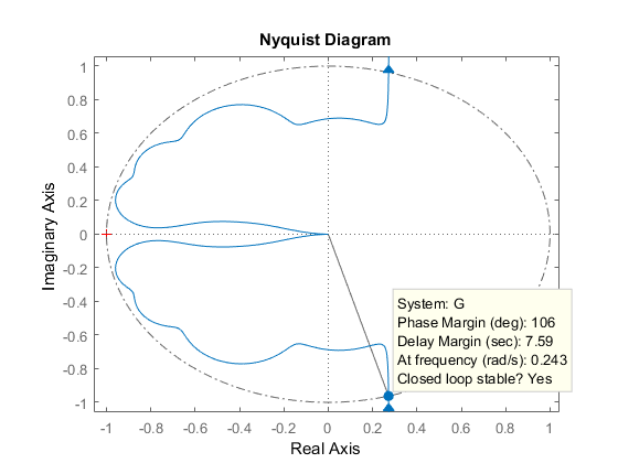
First of all I find it more intuitive to find the gain and phase margins using the Nyquist plot instead of the Bode plot. However, you are correct that the gain and phase margins do give a bit of a narrow minded view on stability margins. Namely, one could construct a transfer function that is arbitrarily close to crossing the minus one point while still having great gain and phase margins, so a small change to both the gain and phase could make the system unstable. One such example would be the openloop transfer function

$$ L(s) = \frac{0.21\,(2\,s + 1)}{s\,(s^2 + 0.8\,s + 1)} \cdot \frac{s^2 + 0.273\,s + 1.43}{s^2 + 0.135\,s + 1.43} \cdot \frac{s^2 + 0.04\,s + 1.56}{s^2 + 0.029\,s + 1.56} \cdot \frac{s^2 + 0.01155\,s + 1.592}{s^2 + 0.0091\,s + 1.592}, $$

where one could get closer to the minus one point by adding more and more inverse notch filters. From the Nyquist plot below it can be seen that $L(s)$ has an infinite gain margin and 106 degrees of phase margin:
enter image description here

However, when applying both a gain and phase shift of only 1.05 and 8.11 degrees respectively the closed loop system (using unitary negative feedback) does already become unstable.

An additional robustness measure one could use is the modulus margin, which is defined as the shortest distance from the minus one point to the open loop transfer function in the Nyquist plot. A more in-depth explanation can be found in this paper in section 4. It can also be shown that the inverse of the modulus margin is also equal to the peak of the magnitude of the sensitivity transfer function and that a given non-zero modulus margin also gives a lower bounds for the gain and phase margin.

At my university they did teach the modulus margin, however I believe many other universities/control theory books only cover the gain and phase margin. Maybe this is they think it is easier for people to imagine how just the gain or phase of a system is changed for example due some amplification or time delay respectively. Or maybe it is because only these two terms became industry standards and the modulus margin did not. It can also be noted that in practice one probably does not often encounter systems like the above $L(s)$, so for most systems it does hold that a good gain and phase margin also implies a good modulus margin. However, your reasoning is correct that the gain and phase margin can sometimes fail and I would encourage you to also use the modulus margin.

$\endgroup$
2
  • 1
    $\begingroup$ I think that for most otherwise sane plants, good gain and phase margins mean a good modulus margin. Certainly the close-loop response of the system you show here would have some sort of bad behavior -- either peaking (in the frequency domain), ringing (time domain), some really weird long over-unity bump in the sensitivity (frequency domain), or some equally weird time domain phenomenon where it almost settles out but then takes forever to finally get to target. Modulus margin is a good measure -- I've certainly applied it in the past, even though I'd never heard a name for it until now. $\endgroup$
    – TimWescott
    Commented Nov 7, 2019 at 23:43
  • 1
    $\begingroup$ @TimWescott Indeed, it also took me a while to construct $L(s)$ as an example where gain and phase margin isn't enough. However, why not use the modulus margin for those edge cases. Plus, as stated in my answer, the inverse of the modules margin is equal to the peak of the sensitivity. So a large modules margin (a rule of thumb is often 6 dB) also guarantees a smaller peak of the sensitivity and thus amplify noise not too much, which sounds like a reasonable design requirement. $\endgroup$
    – fibonatic
    Commented Nov 7, 2019 at 23:55

Your Answer

By clicking “Post Your Answer”, you agree to our terms of service and acknowledge you have read our privacy policy.

Not the answer you're looking for? Browse other questions tagged or ask your own question.