1
$\begingroup$

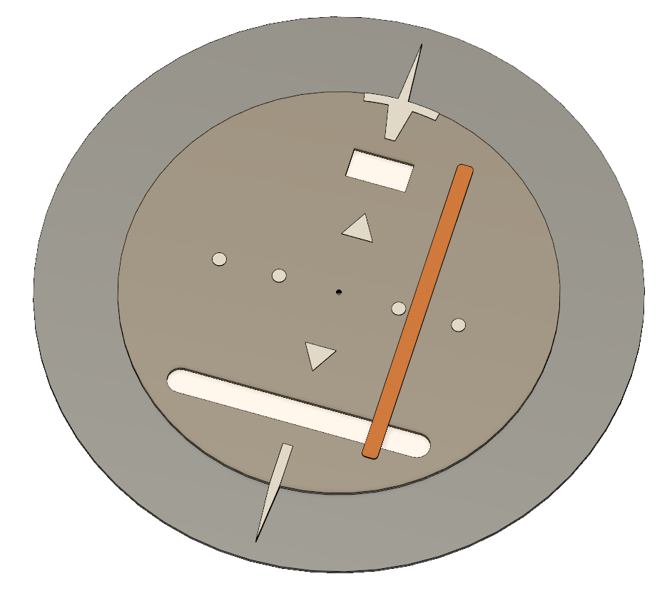
I am trying to design and construct a working replica aircraft instrument (a Horizontal Situation Indicator to be exact) but am facing a couple of issues. The first one can best be demonstrated with the below picture.

enter image description here

The inner disk (brown-ish, including the white markings) can rotate freely around a central axis. The orange bar is fixed to that disk, so it rotates with it. At the same time, the bar should be movable along the slot on the lower part, so with the disk orientation depicted in the picture it would be able to move left and right.

I thought the easiest way to move that bar is using a rack that moves left and right. However, I don't see a way to keep that rack coupled with its driving mechanics throughout the rotation. The goal is for it to be moved completely independently of the rotation.

The first solution that comes to mind is fixing the motor that moves the rack to the disk so it rotates with it and the coupling between the rack and its pinion remains stationary, but that comes with other drawbacks as I'd have to incorporate a slip ring for the wiring and have to deal with the extra torque that is required to rotate the disk to begin with.
$\endgroup$
2
  • $\begingroup$ analog clocks have two or three independently moving pointers $\endgroup$
    – jsotola
    Commented Apr 8, 2022 at 5:39
  • $\begingroup$ Can you post a diagram of how this problem is solved in real life?. As jstola hints, use a second concentric rotary input and then a crank and slider mechanism to move the bar. $\endgroup$ Commented Jan 3, 2023 at 20:47

2 Answers 2

0
$\begingroup$

Assuming you want to use this as a teaching model, because I don't know if they are certified, you can have the lateral deviation indicator's motor connected trough something like these 2-3 wire rotary connectors mounted on your vertical axis.

$\endgroup$
0
$\begingroup$

If you need to do this mechanically, you can use 2 concentric rotary inputs to the inner disk. Then you use a mechanism within the inner disk that moves the position of the inner bar based on the relative motion of the two inputs.

If you used 2 stepper motors as inputs, you would drive them at the same rate to rotate the disk, and at different rates to move the bar.

It would be arrange a differential so that one shaft causes equal rotation of the disk inputs (rotating the disk) and the other shaft causes differential rotation (moving the bar). This may or may not be necessary depending on how you're controlling the indicator.

$\endgroup$

Your Answer

By clicking “Post Your Answer”, you agree to our terms of service and acknowledge you have read our privacy policy.

Not the answer you're looking for? Browse other questions tagged or ask your own question.