4
$\begingroup$

I am tasked with designing a compressed air piping network,with and would like to determine the pressure loss across the different layers of instruments

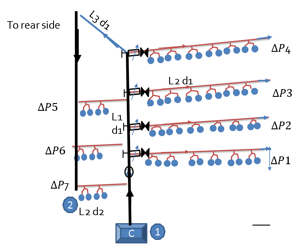
-now here is the 3D layout of the network. The blue circles are instruments I want to deliver air to. They are in parallel with each other and connected in rows parallel to each other. L connotes pipe length (and in some contexts also the vertical elevation) while d is the diameter.

enter image description here

-I would like to find the maximum possible head loss (from point 1 to point 2) given that a proportion of the flow is teed off at each branch. I would also like to find consequently the proportion of flow teed off in each branch.

Am I correct in assuming points 1 and 2 (below) and going about the normal head loss calculation? How do I account for the tees and wyes branching off?

Assumptions

Flow is turbulent

The pressure drop across each brand is designed to be constant (with regulator valves -otherwise they differ due to elevation - maximum between the bottom and the top being 35 meters).
$\endgroup$
5
  • $\begingroup$ Heavily related to : engineering.stackexchange.com/q/21920/10902 $\endgroup$
    – Solar Mike
    Commented Jun 7, 2018 at 18:45
  • 1
    $\begingroup$ You'll want to use the Hardy-Cross Method here. (en.wikipedia.org/wiki/Hardy_Cross_method). A generalized version, using simple friction factors, would be best, so long as you don't approach within 50% of the speed of sound of air in the piping (epublications.bond.edu.au/cgi/…). You'll need to recognize that all air flowing out of the instruments is in fact going to a common outlet (the building), and will have a common pressure value (the building's air pressure), so you will have a fully connected network. $\endgroup$
    – Mark
    Commented Jun 7, 2018 at 19:21
  • $\begingroup$ Potentially relevant previous question: engineering.stackexchange.com/questions/18840/… $\endgroup$ Commented Jun 7, 2018 at 21:56
  • $\begingroup$ @SolarMike apologies, how is it related? it's another question posted by myself but I am still looking for an answer $\endgroup$
    – udidosa
    Commented Jun 7, 2018 at 23:58
  • 1
    $\begingroup$ Each branch off the main line has a regulator valve? How's the control scheme? What pressure & flow rates are we talking about (approx!)? Pressure required at the demand points? I find it confusing that your main pipe and branches are desigated d1 except the main line near pint 2 is designated d2. Can you draw a proper P&ID with all the information you have now? $\endgroup$
    – mart
    Commented Jun 8, 2018 at 9:20

0

Your Answer

By clicking “Post Your Answer”, you agree to our terms of service and acknowledge you have read our privacy policy.