3
$\begingroup$

I have engineering data emerging from more or less complex constructions.

On a regular base I need outlines from construction data to perform geometric calculations on them. The construction data comes from different CAD packages (e.g. Inventor or SolidWorks). I basically need certain closed polygons stored in a way I can read it with primitive methods like sloppy designed PERL programs.

Edit: The polygons are planar. I.e. the data I want to process is 2D. Basically it often is an outline of a 3D object, e.g. a housing.

So my favourite input format for such extracted polygon data is a CSV-file or plain text with whatever separators are available.

As most CAD-SW can import 3D-Models saved in STEP, I practically can choose which software I use to save the polygon data. The outcome is, I will probably end up having DXF or DWG files, which are the most primitive CAD-files I can get from that.

This leaves me with getting my polygons out of that goddamn DXF into a CSV file. Does anyone have an (preferably) easy way to do that?

Addendum: For increased clarificaiton, I describe my task. I have to design PCBs which fit nicely into oddly shaped housings. While my EDA-sw exhibits a fairly usable routine for importing DXF-data, my self programmed autoplacer does not. So in my EDA file, I may have a nice outline, but this does not help me with placing the components inside that polygon. Hence I need the polygon data separately in my autoplacer.

$\endgroup$
4
  • $\begingroup$ Start by explaining what the data is, is it a flat drawing? Or is it a 3D model? But, yes there is no trivially easy way to do this without modifying your approach completely. $\endgroup$
    – joojaa
    Commented Sep 17, 2016 at 6:40
  • $\begingroup$ Why don't you save the CAD geometry into an ASCII STL file and then you can easily convert the face vertices into a list of csv data? $\endgroup$
    – Algo
    Commented Sep 17, 2016 at 18:06
  • $\begingroup$ @Algo: Never thought of STL, as I haven't used that format yet. Will have a look at it. $\endgroup$
    – Ariser
    Commented Sep 17, 2016 at 22:07
  • $\begingroup$ @joojaa 2D. Added that to my question. And never mind my approach. I love to crcumvent any use of Autodesk related file formats. $\endgroup$
    – Ariser
    Commented Sep 17, 2016 at 22:09

1 Answer 1

2
$\begingroup$

It seems you are interested in a flat slice of your CAD model. While you could use a 3D file and slice it yourself that seems like a bit overkill as the CAD application is perfectly capable of doing the slices for you.

quick and dirty

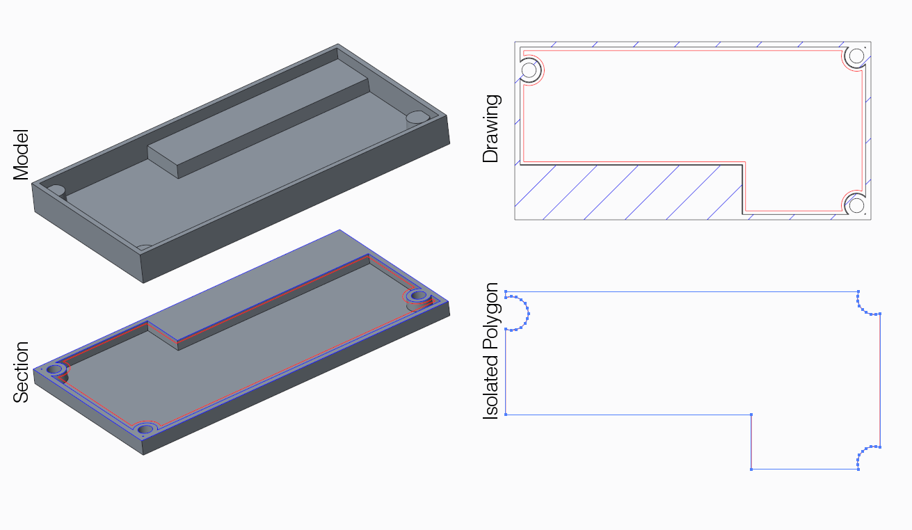
Ok, so each CAD has a 2D drawing mode, you can save that drawing out as dxf or pdf both are easy to parse. If you don't happen to find a good tool for this turn the pdf into svg that can be easier to parse. This approach can also be done quick and dirty by leveraging such tools as Inkscape or Illustrator. Lets do an example because its easy to do:
enter image description here

Image 1: Quick and dirty export drawing as pdf/svg then isolate and read points from that file I used modified version this tool to dump coordinates from pdf. You should be able to do that in Perl easily. data available here

Proper Method

It is possible to access both SolidWorks and Inventor trough a COM bridge so you can access the CAD applications data model directly from your Perl code.This has several benefits but mostly not needing to parse intermediate files. You could select the relevant edges and just traverse them directly from the CAD. Now I only have access to SolidWorks at work but similar approach works in inventor as i have done it.

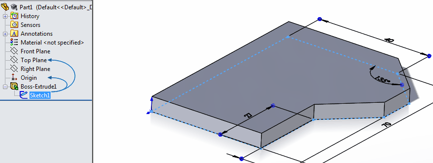
I had some extra time at work to do some quick VBA code for SolidWorks. The code takes all the lines of a closed sketch, sorts them into polygon (with a naive N^2 algorithm) order and prints them in the VBA debug console.

Option Explicit

Sub main()
    Dim swApp                   As SldWorks.SldWorks
    Dim swModel                 As SldWorks.ModelDoc2
    Dim swPart                  As SldWorks.PartDoc
    Dim swSelMgr                As SldWorks.SelectionMgr
    Dim swFeat                  As SldWorks.Feature
    Dim swSketch                As SldWorks.Sketch
    Dim numLines                As Long
    Dim vLines                  As Variant
    Dim dict                    As New Collection
    Dim i                       As Variant

    Set swApp = CreateObject("SldWorks.Application")
    Set swModel = swApp.ActiveDoc
    Set swPart = swModel
    Set swSelMgr = swModel.SelectionManager
    Set swFeat = swSelMgr.GetSelectedObject5(1)
    Set swSketch = swFeat.GetSpecificFeature2

    
    numLines = swSketch.GetLineCount2(1) 'Exclude crosshatch lines
    vLines = swSketch.GetLines2(1) 'Exclude crosshatch lines

    Dim startP, endP, line As Variant
    
    For i = 1 To numLines - 1
        line = Array(Array(vLines(12 * i + 6) * 1000, _
                           vLines(12 * i + 7) * 1000), _
                     Array(vLines(12 * i + 9) * 1000, _
                           vLines(12 * i + 10) * 1000))
        dict.Add (line)
    Next i
    
    startP = Array(vLines(6) * 1000, _
                   vLines(7) * 1000)
    endP = Array(vLines(9) * 1000, _
                 vLines(10) * 1000)

    pp startP
    pp endP
    
    For i = 1 To dict.Count - 1
        endP = NextPoint(dict, endP)
        pp endP
    Next i
End Sub

Sub pp(point As Variant)
    Debug.Print " " & Str(point(0)) & ", " & Str(point(1))
End Sub

Function NextPoint(dict As Collection, point As Variant) As Variant
    Dim i As Variant
    For i = 1 To dict.Count

        Dim data, startRP, endRP As Variant
        data = dict.Item(i)
        startRP = data(0)
        endRP = data(1)
    
        If endRP(0) = point(0) And endRP(1) = point(1) Then
            dict.Remove (i)
            NextPoint = startRP
            Exit Function
        End If
        If startRP(0) = point(0) And startRP(1) = point(1) Then
            dict.Remove (i)
            NextPoint = endRP
            Exit Function
        End If
        
    Next i
End Function

Since vba is calling COM you ca code you can use nearly any language for example perl implements Win32::OLE that can do the job.
enter image description here

Image 2: Example part with simple one loop sketch results in this output

Epilogue

If you really want to export 3D polygon data and do the slicing manually then i would export either OBJ or STL. But this would be way down on my list of approaches mainly because all other approaches are simpler.

$\endgroup$
1
  • $\begingroup$ I could not reach my workstation for some time, but tried your solution. It works fine with simple sketches. Going to try complexer parts, soon. $\endgroup$
    – Ariser
    Commented Oct 13, 2016 at 14:34

Your Answer

By clicking “Post Your Answer”, you agree to our terms of service and acknowledge you have read our privacy policy.

Not the answer you're looking for? Browse other questions tagged or ask your own question.