3
$\begingroup$

I'm working with some flexures (circularly symmetric tube with pins at the ends). Their bending stiffness matches my FEA. However, I'm concerned that they are buckling, reducing their overall axial stiffness.

I don't have a way to measure the axial stiffness in situ; the flexures are part of a larger system.

I don't have a lot of mechanical measurement equipment either, but I do have:

  • Accelerometer
  • Laser distance measurement device
  • Oscilloscope
  • Masses, scales, ...

I can model the buckling, but the rest of the team relies on measurement and doesn't believe models. So, I need to come up with a method of measuring buckling of the flexure in compression.

Ideas?
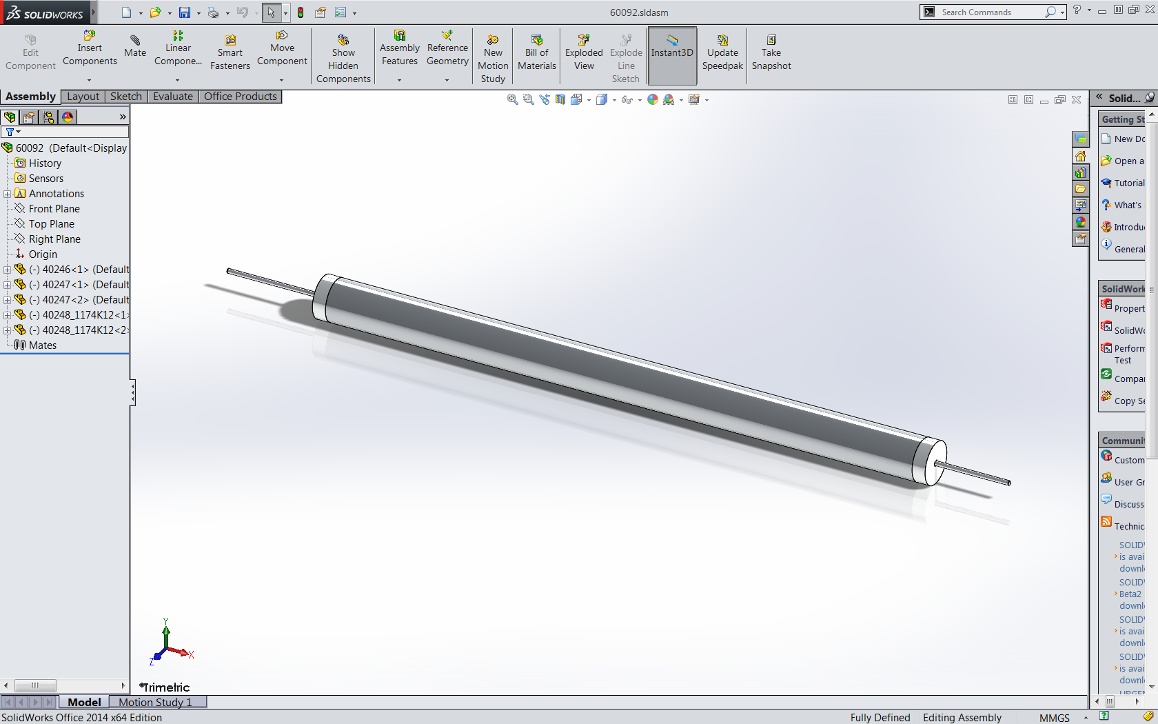
enter image description here

$\endgroup$
2
  • $\begingroup$ What do you mean when you say "flexures"? Do you mean flexure bearings? How would such device be allowed to bend if the ends are pinned? The problem with buckling is that it's very sensitive to the direction of the force applied at the ends of the beam. That can play a large part in the buckling mode, which determines the shape the beam makes when it fails - a 'C' or an 'S', etc. Like with a nil ductility test or similar, the only way you can guarantee to instrument the correct location for buckling is to intentionally create a defect that ensures the buckling mode. $\endgroup$
    – Chuck
    Commented Aug 9, 2016 at 12:38
  • $\begingroup$ It is designed to have both ends fixed (clamped in all 6 DoF's). One end slides laterally with respect to the other. As it does so, it forms and "s" shape. The pins in the end do curve. However, I'm not sure buckling is the correct term. I consider buckling to result in a dramatic drop in axial stiffness - like crushing a can. That does not appear to happen so I want to test for this condition. $\endgroup$ Commented Aug 10, 2016 at 6:01

1 Answer 1

2
$\begingroup$

In principle the axial load in an element is related to its natural frequency. Think of it like a guitar string - increasing the tension in the string raises the pitch (frequency).

It may be possible to attach an accelerometer and then strike the element with a hammer to get it vibrating and measure the natural frequency (or even measure with the laser - if you can get displacement-time with reasonable resolution). If there is a sudden change in axial load (due to buckling) it may be possible to detect this through a change in natural frequency. It would be useful to do some tests before installing the element, or possibly FEA, to see if this is workable and what to expect to measure.

There will no doubt be many issues with practically doing this. Especially since in your case the length is not constant. I'm also not completely certain it will work. However, this sort of thing has been successfully tried before which you can read in this thesis or this article about evaluating the stress in rail tracks.

$\endgroup$
1
  • $\begingroup$ Nice direction. I tried to get the natural frequency in the vertical direction and was unsuccessful. I also tried to get displacement vs. load and was also unsuccessful. I think both can be done, but I need to spend more effort on fixturing. $\endgroup$ Commented Aug 10, 2016 at 20:17

Your Answer

By clicking “Post Your Answer”, you agree to our terms of service and acknowledge you have read our privacy policy.

Not the answer you're looking for? Browse other questions tagged or ask your own question.