3
$\begingroup$

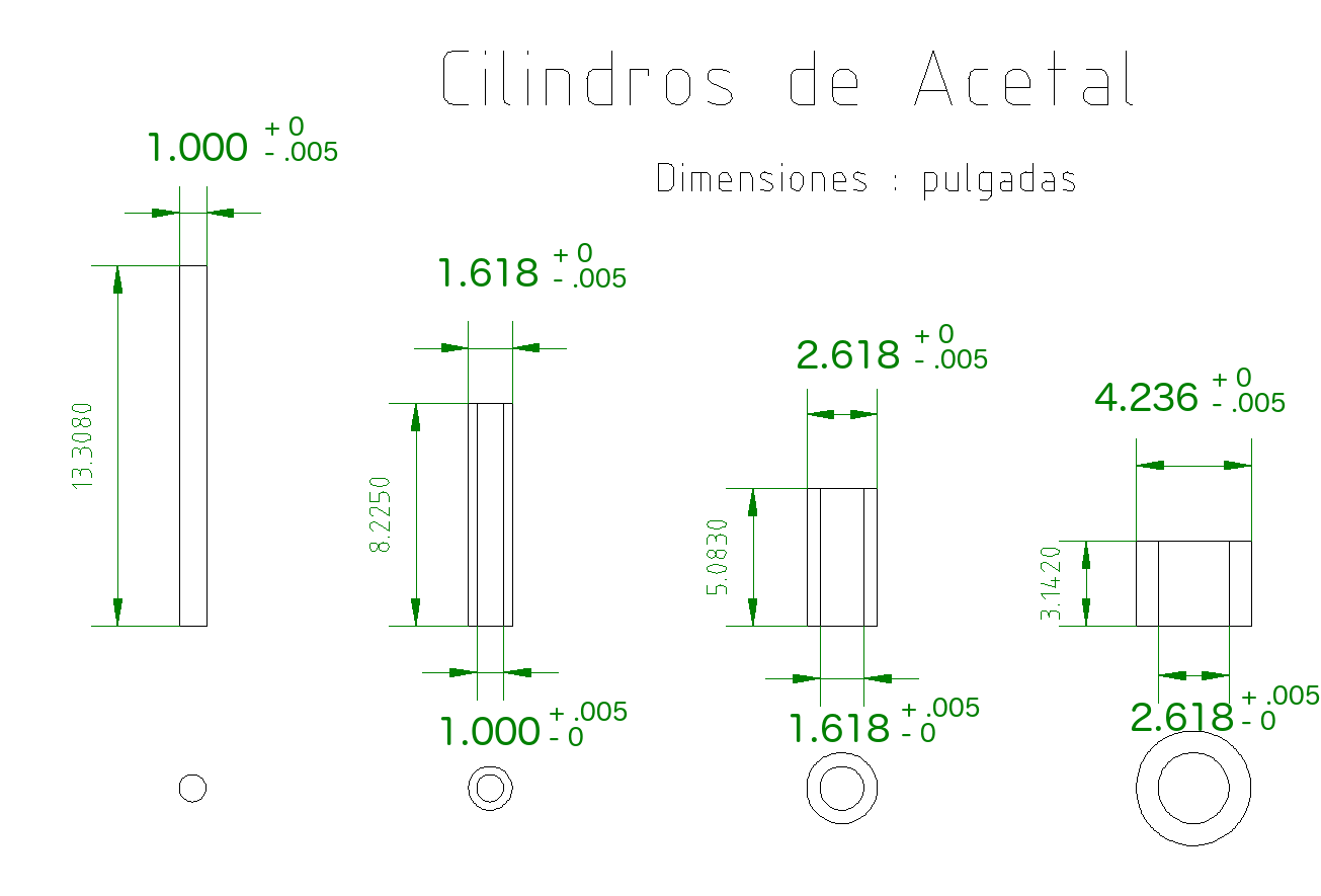
I am prototyping a nested waveguide made of four cylindrical sections. Each piece is turned on a lathe from Delrin (acetal) rod. Each piece fits inside the next larger one.

There are no moving parts. It is an antenna.

My question is: how much larger must the ID of a cylinder be, than the OD of the one which fits inside it?

In my drawing, I have indicated that they be 10 thousandths of an inch larger, but I do not know if this is correct.

I would like to be able to disassemble the cylinders during experiment, to take measurements, and then put them back together.

Each cylinder is to be electroformed with nickel on the outside, so the thickness of the metal layer will also be taken into account.

enter image description here

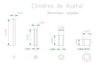
Here is an updated drawing with tolerances added and revised diameters.
enter image description here

$\endgroup$
3
  • $\begingroup$ So are these dimensions showing the finished nickle-plated dimensions or the as-machined dimensions? Can you show/describe how they are used when they are assembled? Do they need to be sealed? How are they oriented? $\endgroup$
    – GisMofx
    Commented Jan 30, 2016 at 13:59
  • $\begingroup$ These are the dimensions of the plastic parts before they are nickel plated. The four cylinders stack inside each other, and sit on a workbench. They do not need to be sealed. They are oriented vertically (as shown). They do not move. $\endgroup$ Commented Feb 1, 2016 at 4:29
  • $\begingroup$ @ShawnLaughlin Yes, your most recent drawing is formatted properly. $\endgroup$ Commented Feb 2, 2016 at 17:05

1 Answer 1

4
$\begingroup$

0.01" is probably a decent place to start as a slip fit, though you can certainly go tighter. I might even question if you actually want a slip fit for this application. You say it's for an antenna, and if you want it to extend and stay extended on its own like other collapsible antennae, a slip fit probably won't accomplish that. You'll need something that creates some friction but not so much that it can't be overcome by a person pulling on it.

In any case, what's potentially more important than the actual dimension is the tolerance. Those nominal dimensions will not be what you actually get, especially when you call out things down to the thousandth of an inch. For a slip fit, how I would actually dimension it is to make the nominal dimensions the same for the inner and outer, and then create a plus tolerance (e.g. +0.005"/-0) on the OD and a minus tolerance on the ID. Using 5 thousandths on each end will get you a 10 thousandths slip at most.

However, you need to know that the place you're sourcing these parts from can match that tolerance. 0.005" isn't that tough for a good machine shop, though I'm not sure how workable that plastic is, I'm more used to dealing with steels and cast irons.

$\endgroup$
4
  • $\begingroup$ @ShawnLaughlin Yes, that's essentially correct. Your meaning is still conveyed, but it is more standard to put tolerances to the right of the nominal dimension rather than below them, though still with the two tolerances stacked on top of each other. $\endgroup$ Commented Feb 1, 2016 at 19:24
  • 1
    $\begingroup$ I agree that .001" is a good place to start, but .010" of total clearance will be far too much for a slip fit. Delrin has a little bit of both give and stretch to it, so with thin walls like that, you could plausibly call out an interference on paper and find that the pieces fit together just fine. I'm not sure how the nickel plating will impact the flexibility of the material. The alternative is to require a tighter manufacturing tolerance, which will increase costs. Just by gut, I'd call for .005" of interference with .003" of tolerance on each side so you have at most .001" of clearance. $\endgroup$
    – Ethan48
    Commented Feb 1, 2016 at 20:11
  • $\begingroup$ @Ethan48 How would you write that on the drawing? Can you point me to a technical drawing image that is an example of this? Is an interference when the OD is larger than the ID which it fits inside? $\endgroup$ Commented Feb 2, 2016 at 2:05
  • $\begingroup$ For example on the inside part: "1.000 +0.000/-.003"" And on the outside part: ".995 +.003/-.000" You might get a slightly better distribution if you gave them a bilateral tolerance like "1.000 +/-.002 and .998 +/-.002" (I used different numbers just because if I did half of .003 we'd have a 4 place decimal which usually suggests even tighter tolerances.) The point is design with some interference because delrin will accommodate it, and just a little too much clearance will cause the assembly to have no holding power at all. $\endgroup$
    – Ethan48
    Commented Feb 11, 2016 at 20:03

Your Answer

By clicking “Post Your Answer”, you agree to our terms of service and acknowledge you have read our privacy policy.

Not the answer you're looking for? Browse other questions tagged or ask your own question.