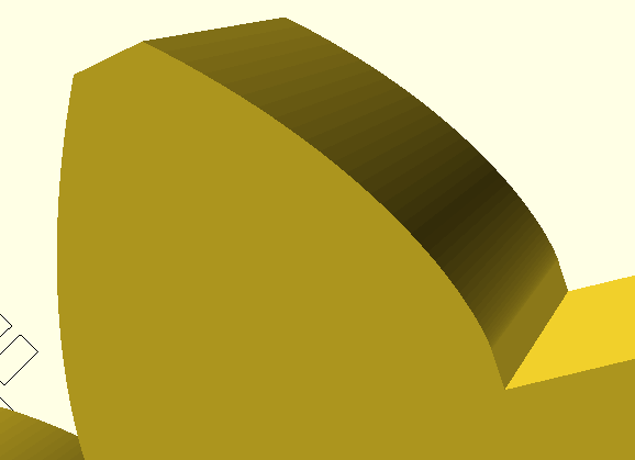
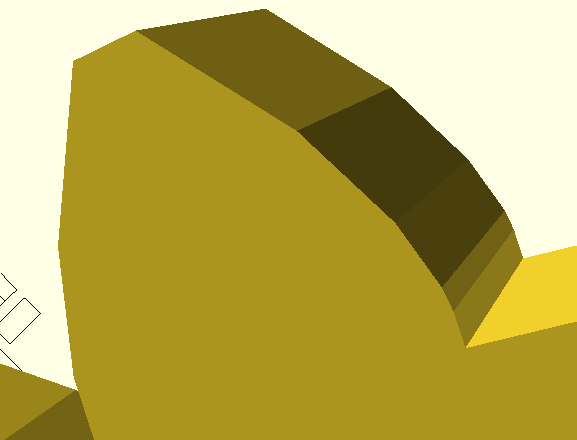
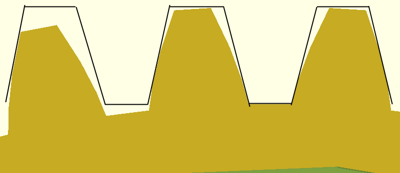
I am facing some issues regarding the kinematic description of a gear mechanism (or maybe more accurately gear manufacturing process). Basically I would like to obtain an animation, where the cogwheel is fixed and the gear rack moves around, but for some reason I cannot reach the result expected.
For the moment I successfully obtained this animation:

Now I got stuck with describing the movement of the gear rack (precisely hob cutting tooth) around the cogwheel. Essentially it means that the entire movement is defined with respect to the fixed coordinate system of the gear wheel, which rotates with the wheel.
My best result so far is the following:
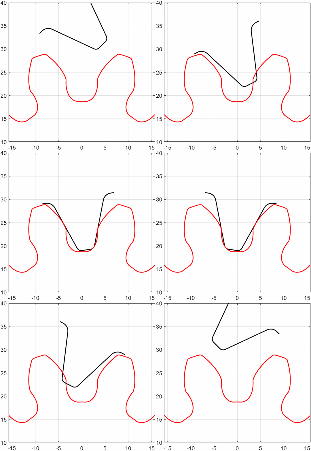
As it can be seen, the tooth goes over the gear wheel, which is obviously wrong.
My mathematical model is described in this picture:
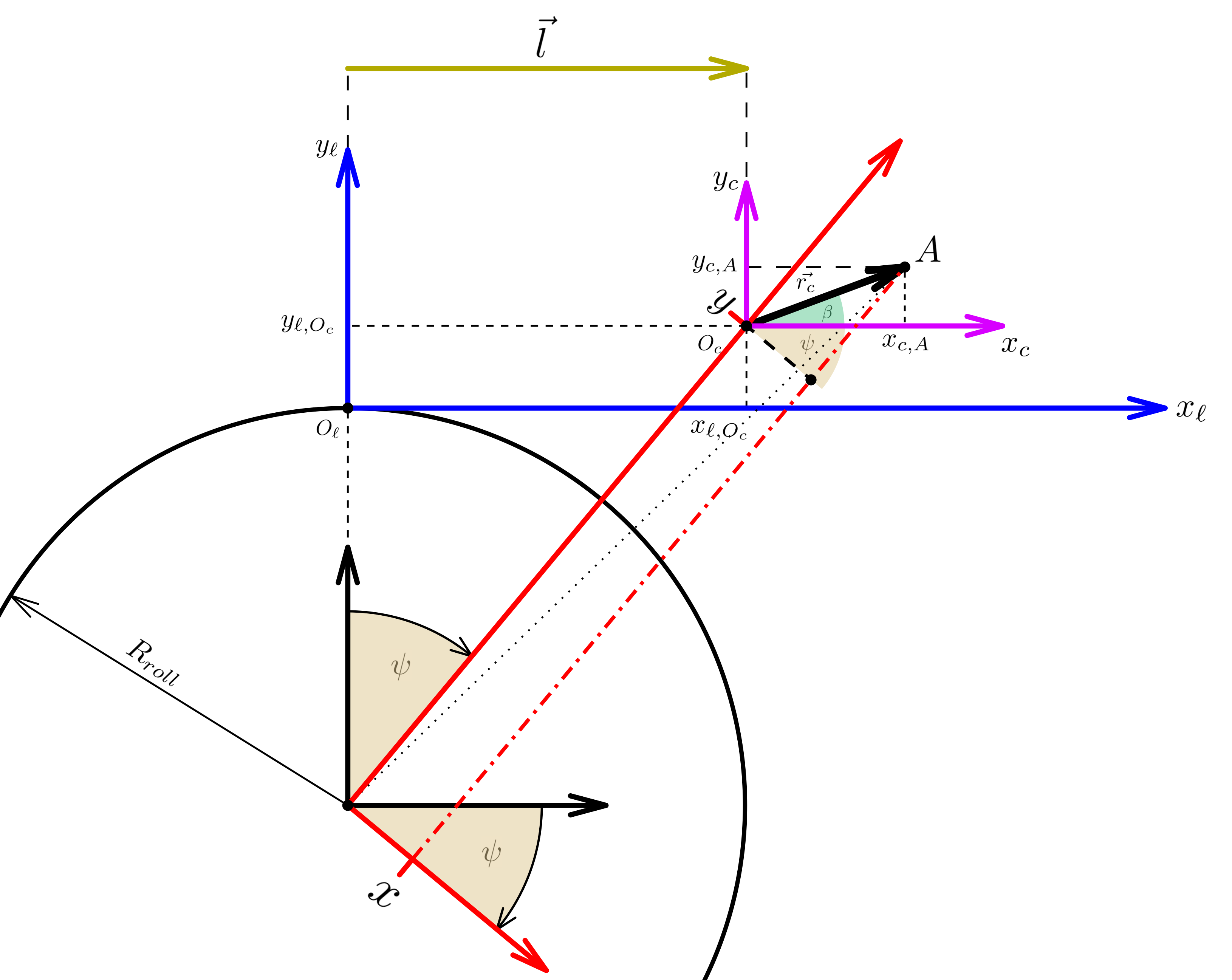
The coordinate system $\left[ x_c, y_c \right]$ moves in the auxiliary coordinate system $\left[ x_\ell, y_\ell \right]$ along the $x_\ell$ axis by the vector $\vec{l} = \left( R_{roll} + y_{\ell,O_c} \right) \tan{\psi} \cdot \vec{i}$, where:
- $\vec{i}$ is the unit vector in $x_\ell$ direction
- $\psi$ is the parameter (and angle as well), which goes through change
- $R_{roll}$ is the radius of the rolling circle
From the image it can be then derived the following:
$x = |\vec{r_c}| \cdot \cos{\left( \beta + \psi \right)}$
$y =\frac{R_{roll} + y_{\ell,O_c}}{\cos{\psi}} + |\vec{r_c}| \cdot \sin{\left( \beta + \psi \right) }$
In this model the coordinate $y_{\ell,O_c}$ represents the possible displacement of the hob from the gear wheel and for this reason it needs to be taken into account. Moreover the vector $\vec{r_c} = \left[ x_{c,A}, y_{c,A} \right]$ is the holder of the hob tooth profile and $|\vec{r_c}|$ is its absolute value, calculated as $|\vec{r_c}| = \sqrt{ x_{c,A}^2 + y_{c,A}^2 }$.
Thank you in advance for any helpful advice
