2
$\begingroup$

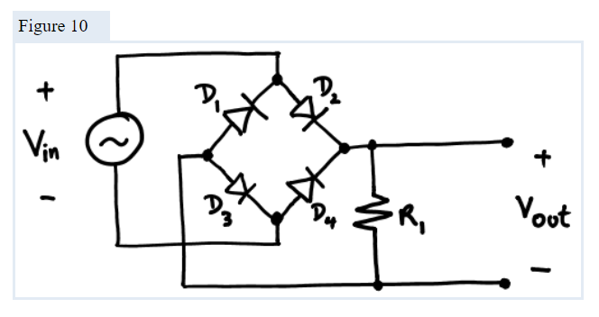
I am trying to convert an AC input into DC output using Diodes, and I found the following diagram for the circuit:

The circuit in question

I understand the diagram, but I don't fully get why the resistor has to be there, assuming that the V_out would be connected to the rest of the system.

$\endgroup$
2
  • 1
    $\begingroup$ It doesn't need to be there. It's probably just a dummy load here so there's current on the output of the rectifier so you can measure the output voltage. $\endgroup$
    – DKNguyen
    Commented Apr 2, 2022 at 3:13
  • 2
    $\begingroup$ should probably consider a capacitor that can handle the voltage if you need something closer to DC. Just be sure to take proper safety precautions since a capacitor does store energy! $\endgroup$
    – Abel
    Commented Apr 2, 2022 at 15:27

2 Answers 2

2
$\begingroup$

Power supply schematics like this one often contain an arbitrary load resistance just to specify where the output of the circuit is taken off. It is not part of the power supply circuit itself.

$\endgroup$
0
$\begingroup$

It could be a part of a bleeder resistor idea for the later part of the circuit.

If there is a capacitor somewhere, it may remain charged for a long time after the circuit is switched off. This may harm a person who opens the circuit or touches the output, expecting there to be no power because circuit is switched off. To make sure this person is safe, a large resistor is added, calculated in a way to discharge the capacitance in a minute or so. Somewhere around 1 MOhm.

If resistance is about 50 Ohm, then it is likely the author put it there as an example of a load, 'connect your load here, like this'.

In any case, this resistor is not strictly needed for this circuit to operate.
$\endgroup$

Your Answer

By clicking “Post Your Answer”, you agree to our terms of service and acknowledge you have read our privacy policy.

Not the answer you're looking for? Browse other questions tagged or ask your own question.