0
$\begingroup$

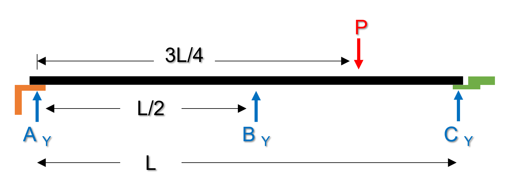
I need to analyze a continuous beam of length L and three supports: A (at x=0), B (at x=L/2), and C (at x=L). An applied load P is applied at x=3L/4. Now, at A, the continuous beam is bolted to a bracket (drawn in orange). At C, the continuous beam is bolted to another bracket that is welded to another beam (drawn in green), at its midspan (see the image attached). The beam with the welded bracket is perpendicular to the continuous beam.

If I'm not mistaken, the bracket acts like a cantilever beam, and the applied load causes torsion on the perpendicular beam due to the bracket welded. I tried finding the reaction forces using the superposition method for statically indeterminate beams, described in many MoM books (I consulted Philpot's).

According to this method, when dealing with a beam supported by another beam, a compatibility equation must be used, after determining the deflections at the point of interest. The first step when solving this type of problems consists of eliminating the redundant reaction (let's say A, in my structure) and finding the other reactions (B and C) using static equilibrium equations, since eliminating the redundant reaction leaves a statically determinate beam (released beam). In my case, I find that following these steps don't really apply, because reaction force C is determined once a compatibility equation is used when finding deflections at point C. It is something like a paradox: reaction force A is found by finding reaction C, but reaction C is found by finding reaction A, and so on. How can I solve this issue? Is there another analytical method that tackles these cases? Am I just doing something incorrectly? Am I on the edge of discovery of a new MoM method? (just kidding).enter image description here
$\endgroup$

2 Answers 2

0
$\begingroup$

The brackets don't play a role unless they have some Moment or external load acting on them, or their self-weight is significant, which is not shown here.

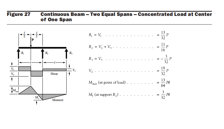
This is a typical problem and the solution can readily be found in many design aids. by searching for a two-span beam with a concentrated load on the mid-span. An easy way of calculating the reactions is to release the third support, C, and let the C node deflect up, and then calculated the reaction at C the would cancel the deflection as you mentioned compatibility method.

The figure below is the moment and reactions by the DNS design aid. source.

.

DNS design aid

$\endgroup$
0
$\begingroup$

This answer is to point out the possible reason for the "wrong" result getting from the superposition method.

  • The method of superposition is valid and is desirable for this problem, but your assumptions on the support rigidity could have been wrong, thus causing the mistake.

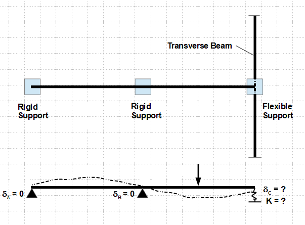
The end of the beam on the right (point C) is sitting on another beam that is deflectable and should be modeled as spring support as shown on the graph below. The strength of the spring constant is influenced by the characteristics and properties of the transverse beam - length, stiffness, support conditions, and deflection at point "C".

enter image description here

The first step in solving this problem is to determine the stiffness of the spring. Let's isolate the transverse beam, and apply a unit load ($P = 1$) at point "C". The spring constant is then equal to the unit load divided by the deflection found at "C", $K = 1/\delta_{C1}$. From here on, everything is back on the track. ($\delta_{C1}$ is the deflection at point "C" due to the unit load $1$.)

$\endgroup$

Your Answer

By clicking “Post Your Answer”, you agree to our terms of service and acknowledge you have read our privacy policy.