2
$\begingroup$

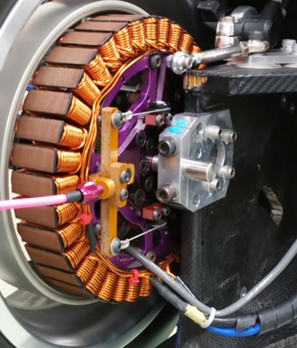
(I feel it is necessary to mention that I am not an electrical or mechanical engineer; I just like to build fun things.) I've already got a good explanation of the concepts involved in a variable field magnetic motor, but how is it achieved? It surely can't just be a DC motor with a retractable stator, right?

Here's an example of what I'm trying to make: https://www.youtube.com/watch?v=olnXy-J48SY

It really does look like a simple DC motor, but every one of these I've seen has that brown padding at the top of each armature loop. Is it something vital to the contraption?

I've scoured the internet, but there isn't a whole lot that goes further into this than the concepts involved. I realize this may force you to dead-reckon, but I'm desperate for information by now.
$\endgroup$
1
  • 1
    $\begingroup$ Are you expecting us to watch the video and write a parts list and step by step instructions? I suggest you should do that as an essential part of your learning experience. $\endgroup$
    – Solar Mike
    Commented Mar 16, 2021 at 6:35

3 Answers 3

0
$\begingroup$

It is just a three-phase brushless DC (BLDC) with a retractable stator!

可変界磁 ダイレクトドライブモーター  variable field magnet motor.

Bigger motor, same source. You can clearly see Red, Blue & Black wires going to motor.

enter image description here

Magnets are on rotor. Stator is made up of laminated steel segments to decrease hysteresis. Coils are wrapped around stator poles.

$\endgroup$
2
  • $\begingroup$ Thanks for the simple answer! I was really questioning myself when I came to the conclusion that it's just a brushless DC motor, especially given that the stator-teeth all had this mysterious brown padding. Never would've guessed the stator material is a critical component, either. Thanks again! $\endgroup$
    – Alex
    Commented Mar 16, 2021 at 20:13
  • $\begingroup$ There is no uncritical component. $\endgroup$ Commented Mar 17, 2021 at 0:15
2
$\begingroup$

Variable Field magnetic Motor can mean different things depending on the context. What I saw in the video is completely different to what I thought when I read the title of the question.

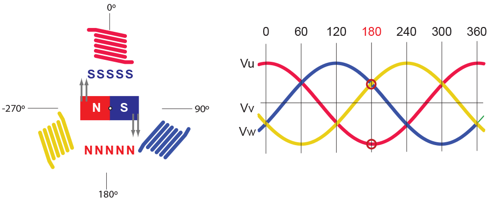
The first thing that sprung to mind was Field Oriented Control (or Vector Control). FOC is a type of control that modifies the magnetic flux (thus Variable Magnetic Field), in order to achieve maximum torque and variable rpms.

Basically the way it works ( in one of the implementations ), is that the current in each winding is controlled in such a way so that the magnetic flux in the system is such that the rotor rotates in the desired rpm and torque.

enter image description here

This type of control can be used to different types of motors:

  • DC Brush,
  • Brushless DC (BLDC) and
  • step motors
  • AC induction motors (sensorless field control)

So (at least the way I understand it), you can't really build a Variable Field Magnetic Motor. There are many hardware implementations of motors, that can be controlled with a varying magnetic field.

PS: I am not an expert in the field.

$\endgroup$
0
$\begingroup$

Although the previous answers address the OP's question, I am adding an answer since they do not explain the mechanism of the variable field magnetic motor.

The variable field magnetic motor is usually built as a brushless DC motor (BLDC). The mechanism works by moving the rotor out of line with the stator so the effective magnet strength is lower. This increases velocity constant $K_v$ because the motor has to run faster to produce enough back-EMF to counter-match the supply voltage. It is the permanent magnet equivalent of varying field current in a shunt-wound motor. Indeed, motor speed could be raised by simply increasing voltage, but this also increases material (iron) losses due to hysteresis and eddy currents. Field weakening reduces the magnetic field strength as it raises rpm, reducing the loss at light loading. However it also reduces torque and output power, so it is more suited to applications which require high efficiency at both low rpm & high torque and high rpm & low torque.

Here is a video showing the increasing speed of the rotor with decreasing cross sectional interface between the curved surfaces of the rotor and stator.

$\endgroup$

Your Answer

By clicking “Post Your Answer”, you agree to our terms of service and acknowledge you have read our privacy policy.

Not the answer you're looking for? Browse other questions tagged or ask your own question.