2
$\begingroup$

I have inherited a DIY build and I have some doubts about its design. Have a look at the following diagram: enter image description here
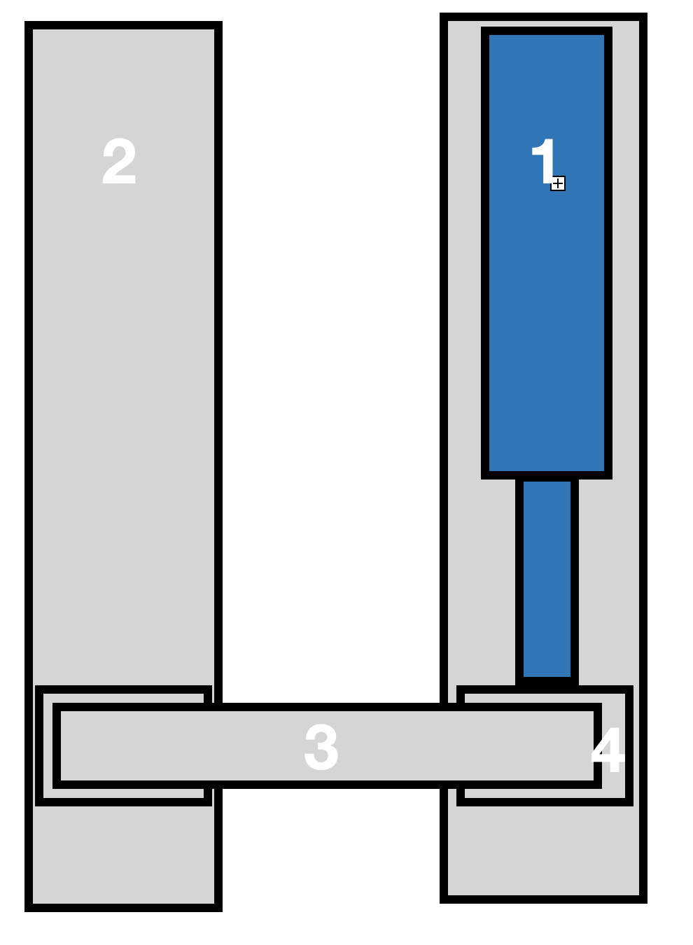
1 is the linear actuator. It's quite beefy 2000 lbs 12" stroke. It is installed in an aluminium channel. 4- Is a carriage, essentially a box section with little rollers on all sides, so it has no play within the channel and moves quite smoothly. This is connected to the actuator's rod. 3. Is a flat steel bar that links to an identical channel (2) and carriage assembly, though this doesn't have an actuator in it.

The system is supposed to lift a max 220 lbs load that is evenly distributed along the bar.

My questions are:

  1. While there don't seem to be any bending forces to the actuator itself, is it a safe design, as far as longevity of the components goes?
  2. is there anything I can do in channel 2 to support the system, e.g. a spring at the bottom, etc. to address any design problems?
$\endgroup$
3
  • 2
    $\begingroup$ I think a lot depends on the interface between 1 and 4 and on 4 generally. Can you post fotos? How long is 3? I think it will boil down to how much 4 deforms under load. $\endgroup$
    – mart
    Commented Oct 27, 2020 at 16:49
  • $\begingroup$ The devil is in the details. Please post some photos if possible of the joint between 1 and 4 and also the rail system in 2 and 4. $\endgroup$
    – NMech
    Commented Oct 27, 2020 at 17:28
  • $\begingroup$ As people have said it depends on the details, one thing you could do is if you can power both directions you could put a continuous Force spring on beam number two to offset a portion of the weight. $\endgroup$
    – MadHatter
    Commented Oct 31, 2020 at 17:12

1 Answer 1

2
$\begingroup$

As a quick basic estimation approach we annotate the following:

  • The length of bar 3 = L

  • Top and bottom bearing force on each box $F_b$

  • The height and width of boxes 4 and its counterpart on channel 2 H and W. $$ \Sigma M=0 ,\quad 220*L/4 = H/2*4F_b \rightarrow \quad F_b=220*L/8H $$

Now you have to figure if the bearings and their connections are okay to take this load multiplied by a safety factor of say 3.

$\endgroup$

Your Answer

By clicking “Post Your Answer”, you agree to our terms of service and acknowledge you have read our privacy policy.

Not the answer you're looking for? Browse other questions tagged or ask your own question.