0
$\begingroup$

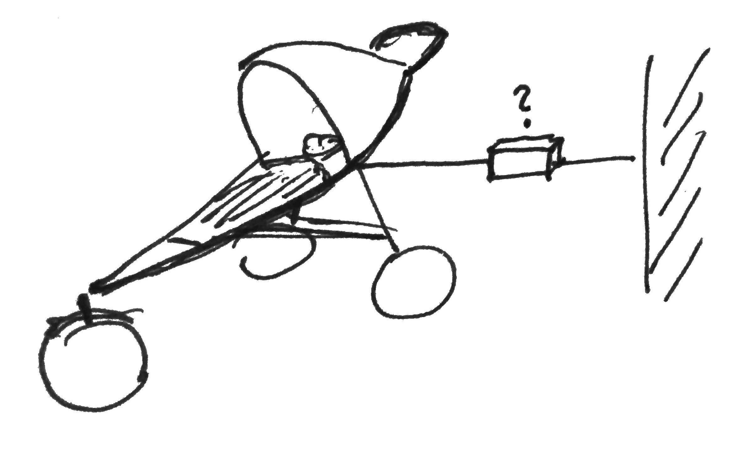
I just came back from a walk with my 4-month-old. He's sleeping in his pushchair. I am sitting next to the push-chair and slightly pulling the pushchair's side so it gently rocks from side to side in it's resonant frequency. This motion is what keeps my son asleep. I estimate that I am keeping about 2.5 Hz oscillation with amplitude around 10 mm, my finger is pulling with force around 2 N each cycle. The oscillation is damped a lot.

So I am sitting there, keeping the oscillation going, thinking... How to automate this? What device could be pulling the pushchair so I can make myself a cup of tea?

As a fun challenge, will you help me find/design a device to do this?

Constraints:

  • Electro-mechanical, may have a micro-controller
  • Has to be easy to tune the frequency. Or even better find it itself.
  • As a bonus it could adjust to a range of amplitudes
  • It has to be safe = not produce massive G-forces
  • Preferably it should be pulling a string or rope that I will fix to a wall.
  • A prototype has to be pulled off by me:
    • off-the shelf parts, Lego Technic, re-purposing something ...
    • some experience with similar crazy one-of-a-kind builds :)
    • basic soldering and electrical-engineering skills
    • software engineer, programming a microcontroller is not a problem
    • some woodworking skills
    • can order a 3d print
  • under 50 USD in material

So far I am imagining a servo pulling a rope that will be controlled by a microcontroller. I am thinking if it would be possible to attach an accelerometer to the push-chair to find the resonant frequency.
enter image description here

$\endgroup$

3 Answers 3

2
$\begingroup$

Why not check out a wiper motor? Cheap, easily available from a scrap yard and available with 2 or 3 speeds. Also sorting 12v power is not difficult as well as cheap motor speed controls can be had.

They usually drive a linkage, so working out where to connect to get the travel you desire is relatively easy.

$\endgroup$
1
  • $\begingroup$ I wish I had included that option in my answer. Pretty obvious once it's out in the open. $\endgroup$
    – fred_dot_u
    Commented Oct 16, 2020 at 14:43
1
$\begingroup$

Consider the lowly circle. It's used in a variety of mechanical devices, including piston engines as a component of a crankshaft. With a disk of sufficient diameter, one can place the rod portion along the radius in almost any location, which provides for adjustable amplitude.

The disk can be driven in any number of ways, from gears, including planetary gearsets, to belts and other less-practical methods like a fan blowing on vanes. Speed adjustment comes from the selection of motor, motor control and gearing ratios.

I don't think you want the flexibility of a string attached to the wall, as that would require that the trolley provide the resistance. Relying on the trolley to not-move is less stable than a push-pull design as noted above.

Damping could be provided by having a flexible joint at the pivot on the disk. Allowing for exaggeration for the purpose of demonstration, envision that the rod has a coupler at the disk end containing an embroidery hoop, for lack of a better representative circle. The hoop is secured in four to fifteen locations from the rim to the disk pivot location.

As the disk rotates (slowly), inertia keeps the hoop in the original location, until sufficient force has been applied to the rubber bands. Now the hoop pushes the rod, beginning the rocking. As it rotates, the mechanism "catches up" and the rubber bands attempt equilibrium. At the reversal point, inertia once again causes the bands to stretch in the opposite direction.

There would be other methods of providing similar damping, including telescoping tubing from the disk to the trolley with pistons and valving to regulate the compression strokes.

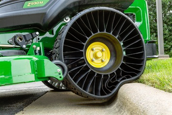
I've used casting silicone which could take the place of the rubber bands in the above description if the hoop portion was thick enough. Even casting the silicone in a shape similar to that of flat-free mower tires would create damping and absorb some of the force. Turf Magazine provided this image, just like the mower I saw yesterday:

flat proof tire

There are so many variations from the above description as to make this question at risk for the "too vague" closing, but you've provided parameters that reduce this somewhat.

I could also picture a rig under the wheels on one side. The motor shaft has a cam which alternately raises and lowers that side of the trolley. Again, gearing plays a big part in this concept. Damping and resonance can be adjusted with cam diameter and motor speed.

For your objective, I believe that a micro-controller device may be excessive, although possibly fun for the exercise. On the excessive side, I'd sketch up a four bar linkage just to see what could be done with changing link lengths and pivot locations.

$\endgroup$
1
$\begingroup$

There's a product: http://www.lolaloo.com/en/

Motors and gears are loud, likely too powerful (and dangerous), and may not easily match the required speed range. I once coupled a wiper motor with lever via a long spring to a baby's hammock. It worked OK, but it's not an oscillation, it's noisy, and it's dangerous.

I'd consider a super-sized version of a "beckoning cat" (and lots of similar toys) that essentially is a pendulum with a magnet and simple circuit to give it an electromagnetic push. This would not need a microcontroller, but it may be implemented with one.

$\endgroup$
1
  • 1
    $\begingroup$ Also consider that you'll only "need" this maybe for another 6 months or so at most... :-) $\endgroup$
    – handle
    Commented Oct 28, 2020 at 7:20

Your Answer

By clicking “Post Your Answer”, you agree to our terms of service and acknowledge you have read our privacy policy.

Not the answer you're looking for? Browse other questions tagged or ask your own question.