1
$\begingroup$

I’m not an engineer, however I think this place is the best one to find an answer to my question.

So my problem is as follows: I need to create a mechanism, preferably driven by a dc motor, that will hit the surface above it as hard as possible for a small DC motor. Like a sort of hammer, that is supposed to hit the surface above it (above is the keyword, I found DaVinci’s hammer mechanism, but it works based on gravity, which is not really helpful in the opposite direction). I’ve tried to research rotary to linear mechanisms, but all of them look like they will stop when the linear part hits the surface above and cannot go further. Can you suggest something?

$\endgroup$
1
  • $\begingroup$ Is pressurized air out of question? $\endgroup$
    – joojaa
    Commented Jan 17, 2019 at 6:06

2 Answers 2

1
$\begingroup$

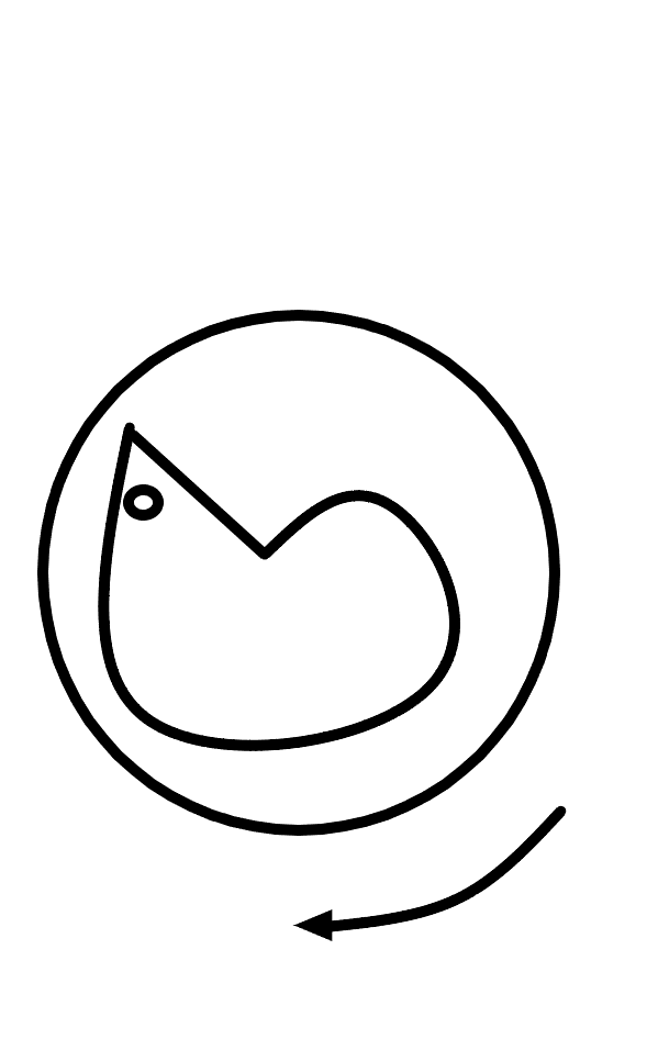
check this graph, cam hammer

Now if you attach a spring loaded vertical ramrod released upwards when the little roller cam, bearing inside this rotating gear falls into the step, you have your hammer.

It is based on Leonardo De Vinci's hammer, except like a negative or reverse mechanism. the cam is inside the gear not outside.

$\endgroup$
1
  • $\begingroup$ Definitely, impact with spring, drawing the spring with the motor. The cam mechanism is a matter of specific design, but the core concept should definitely involve a spring to provide the impact force. $\endgroup$
    – SF.
    Commented Jan 17, 2019 at 14:21
0
$\begingroup$

A consideration of an upward-striking hammer is that you have to have some method of preventing damage to the mechanism as the hammer reaches the surface being struck. This could be the absorption of energy or the displacement of the item/surface being struck. Recoil is the method used in the gravity-fed DaVinci design.

A couple of methods come to mind, but I'll focus on one. Consider DaVinci's design, but place the cam under the lever end containing the hammer. As the cam rotates, the hammer falls to a conveniently placed platform.

The other end of the lever is extended and also has a hammer head attached. As the cam rotates and the first hammer falls, the second hammer rises. It should be configured to strike the desired surface before the first hammer contacts the platform, for optimum results.

In the above described configuration, the weight on the first hammer end has to be greater than that on the second hammer end. The placement and size of the cam allows for flexibility. One could place the cam outboard of the first hammer head and have a substantial size and displacement, for example.

You've noted that the mechanisms you've found appear to stop the hammer at the upper surface. This is to be expected if you are striking this surface. Will you expect your upward-striking hammer to move the surface it strikes?

If so, your design will have to allow for greater travel via cam diameter, displacement and location along the lever.

If this does not appropriately address your design considerations, please provide additional constraining criteria.
$\endgroup$

Your Answer

By clicking “Post Your Answer”, you agree to our terms of service and acknowledge you have read our privacy policy.

Not the answer you're looking for? Browse other questions tagged or ask your own question.