1
$\begingroup$

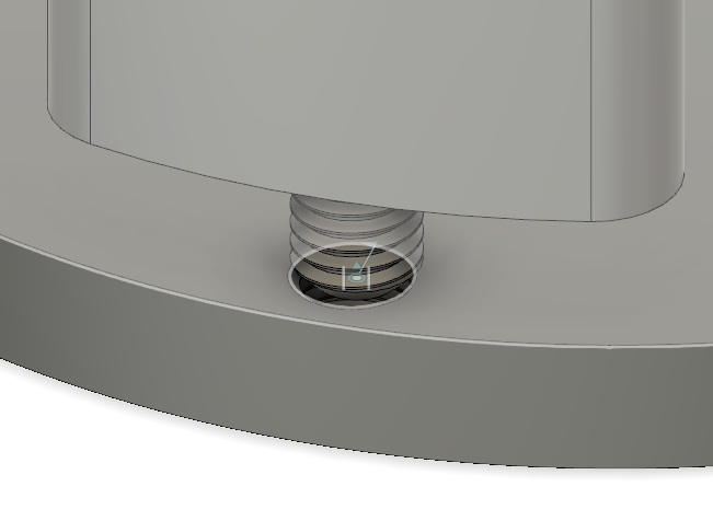
I have a simple thread joint between two objects:

enter image description here

and want to find a size of those threads so that after rotating male part it stands at the specific angle. For those who is curious I made it in Fusion 360 and added joints to these parts, also specified limits of sliding upward and downward. The problem is when it totally rotates till the end, the upper part stands in the wrong direction. I am going to 3d print it, so I need it to be as precise as possible.
$\endgroup$

3 Answers 3

3
$\begingroup$

Well I would suggest that you don’t thread one of the items - just have a clearance hole then a locking nut.

Then, to get a precise position have a hole with a locating pin - this will ensure the positioning.

$\endgroup$
0
$\begingroup$

Thread joints are for animation; sounds like you were using them for design.

Could you:

  • Have threads made to both parts; you can use section analysis to see that they match
  • Place the parts together (the end result)

If you want the animation, start the thread joint from there.

I think your problems were due to trying to land at a good end position, but if you take it the other way round, would it work?

$\endgroup$
0
$\begingroup$

For serious answers finite element analysis and physical testing are used. The oil industry uses hundreds of different threads for casing and tubing ; these connections are very highly loaded , under very high pressures and need to be leak tight so the costs of FEM and testing are warranted.

$\endgroup$

Your Answer

By clicking “Post Your Answer”, you agree to our terms of service and acknowledge you have read our privacy policy.

Not the answer you're looking for? Browse other questions tagged or ask your own question.