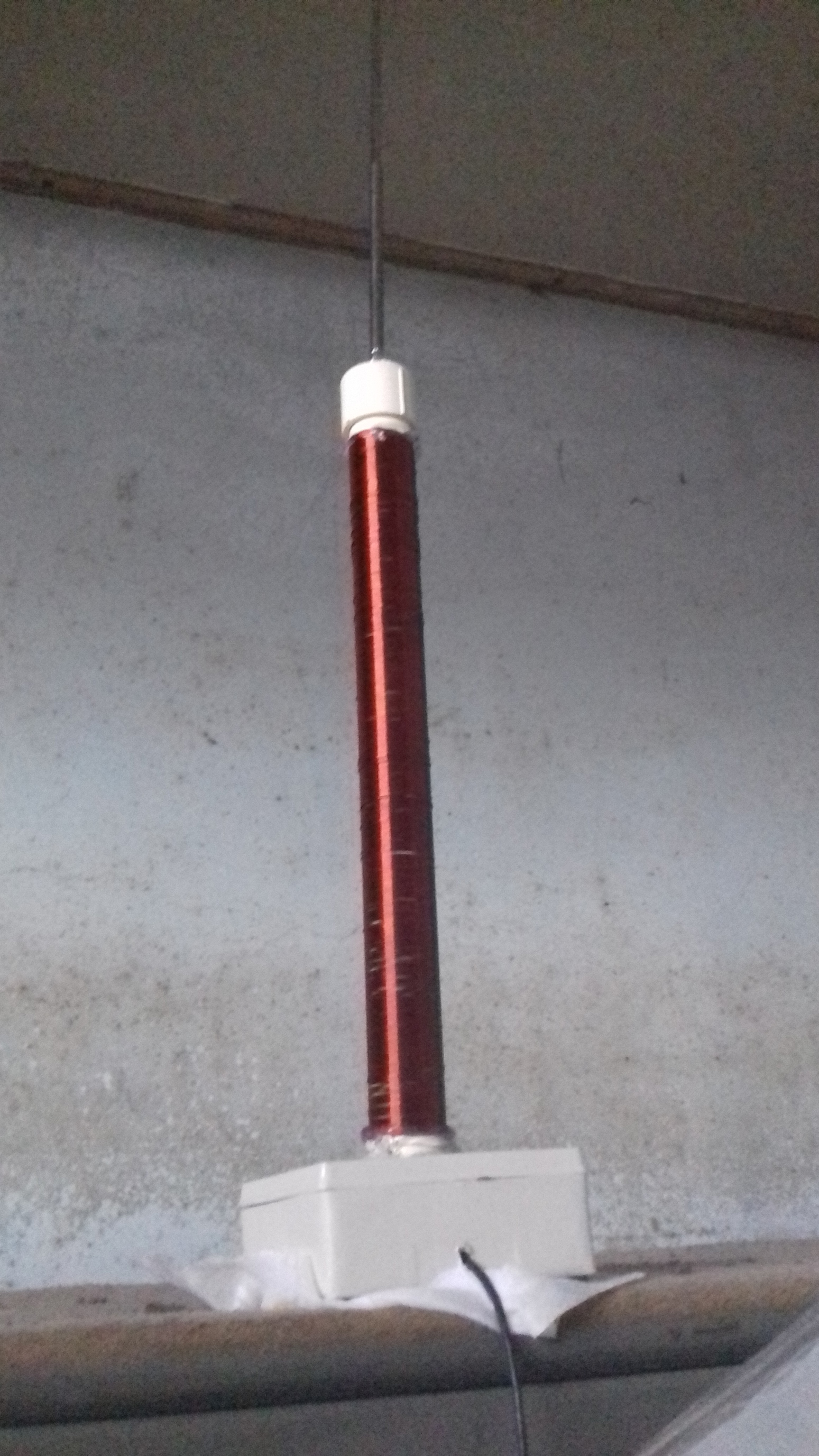
Every radio antenna works in the same way. In receiving they catch a part of the radiowave. The caught part is directed along a wire or somehow more carefully designed transmission line into receiver's circuits. Often any separate transmission line doesn't even exist. The antenna is simply a wire or plate which is connected straight to the receiver circuitry. The electromagnetic field of the caught wave generates current to the circuit. It's filtered, amplified and finally converted to usable audio, video or data signal.
In transmitting operation AC current is fed to the antenna for example by connecting the antenna to an AC voltage source (radio transmitter is one) and the antenna emits an electromagnetic wave.The radiation can be remarkably strong if the antenna is properly engineered based on Maxwell's theory of electromagnetism. Or the antenna is made accidentally to be proper for its purpose. It can happen, but generally radio transmitters suffer badly (overvoltage peaks, heating) if the antenna is not properly designed. Radio receivers can often get an usable signal from an antenna which is not at all good to be connected to the output of a radio transmitter. That's because radio transmitters often are designed to use the parts at their limits and there's not much room for unexpectedly high currents and voltages.
In receiving one can easily lose say 99% of the theoretically available caught power (less than a microwatt) if the remaining 1% is enough for the receiver. A HF radio receiver can often detect signals from the other continent with a quite random wire antenna, like your linked Sony and Sangean types. If you try to send an answer with the same antenna you are lucky if your transmitter does the job. At least yo need an effective antenna tuning apparatus.
Designing an antenna is a demanding math challenge, far beyond the math skills of most of us. Radio amateur books present successful design results and there's as well numerous experimental results of successful tireless hobbyists. Use them. Half wave dipole and quarter wave whip are well known such results. Do not make lousy assumptions like "this antenna is said to be 50 % shorter than the theoretical quarter wave whip and it is still said working ok, because it has a lenghtening coil -so I need no whip at all if I have 2 coils in series!"
Rabbit ear whips in data networking routers and wireless mic receivers are separate antennas for separate radio receivers which are there to make possible to have more than one simultaneous radio paths. An alternative path increases substantially the probability of error free reception. In old portable FM radio receivers a pair of whips was a commercial gimmick to make the device look more attractive for a potential buyer. It was a materialized version of advertising terms "super", "hyper", "ultra", etc... In theory the 2 whips could be a half wave dipole, but the rest of the radio alone could be as good counterweight for one whip.
