0
$\begingroup$

I am very new to GD&T and currently working one of my first drawings for two parts (see simplified drawing below). For accurate alignment during assembly each of the parts has two locating features (A: two slots, B: the counterparts to A's slots). After assembly, the distance between fits F1 and F2 and their diameters are the basically the only dimensions which need to be controlled to (somewhat) tight tolerances, two gears will be fit at those features.

Since the parts are quite flat, the bottom of each part is a good choice for the first datum (A). However, I am currently struggling with how to define good features for the other datum(s) which match my design intent (without needing to apply overly strict tolerances). What would be your recommendations for a defining good datums?
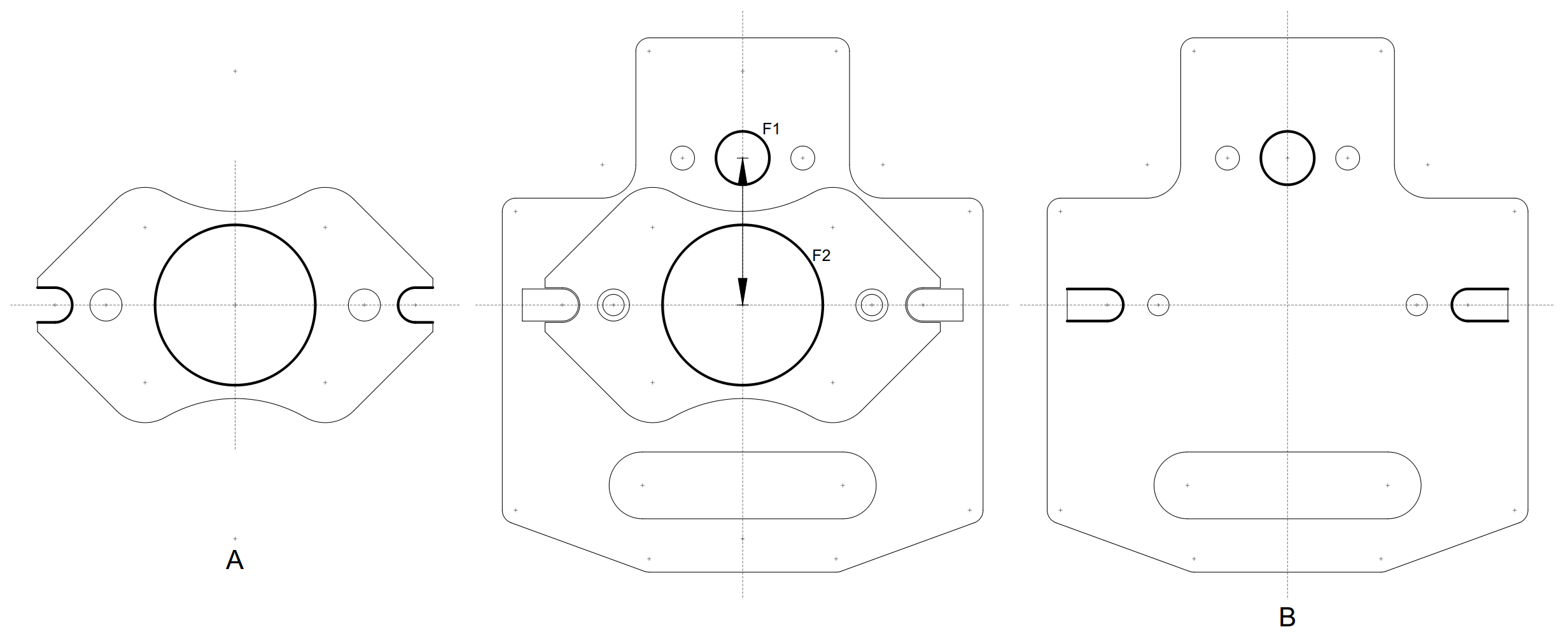
Drawing

$\endgroup$
2
  • $\begingroup$ Usually there are two ways to build the tolerances on your drawing: a) deriving it from the function only, not considering the production process; b) using the manufacturing sequence. Which one would you need? And which system would you prefer: ISO or ASME? $\endgroup$
    – Tawhiri
    Commented Nov 22, 2022 at 17:47
  • $\begingroup$ I prefer the ISO system. Not sure if a) or b) would be better in my case. $\endgroup$
    – raisyn
    Commented Nov 22, 2022 at 22:41

2 Answers 2

1
$\begingroup$

If you have a machine shop on-site, go down there and show the drawing to the machinist and ask him where to put the datum where it makes the most sense from a metal-cutting standpoint. This will make him your friend.

$\endgroup$
1
$\begingroup$

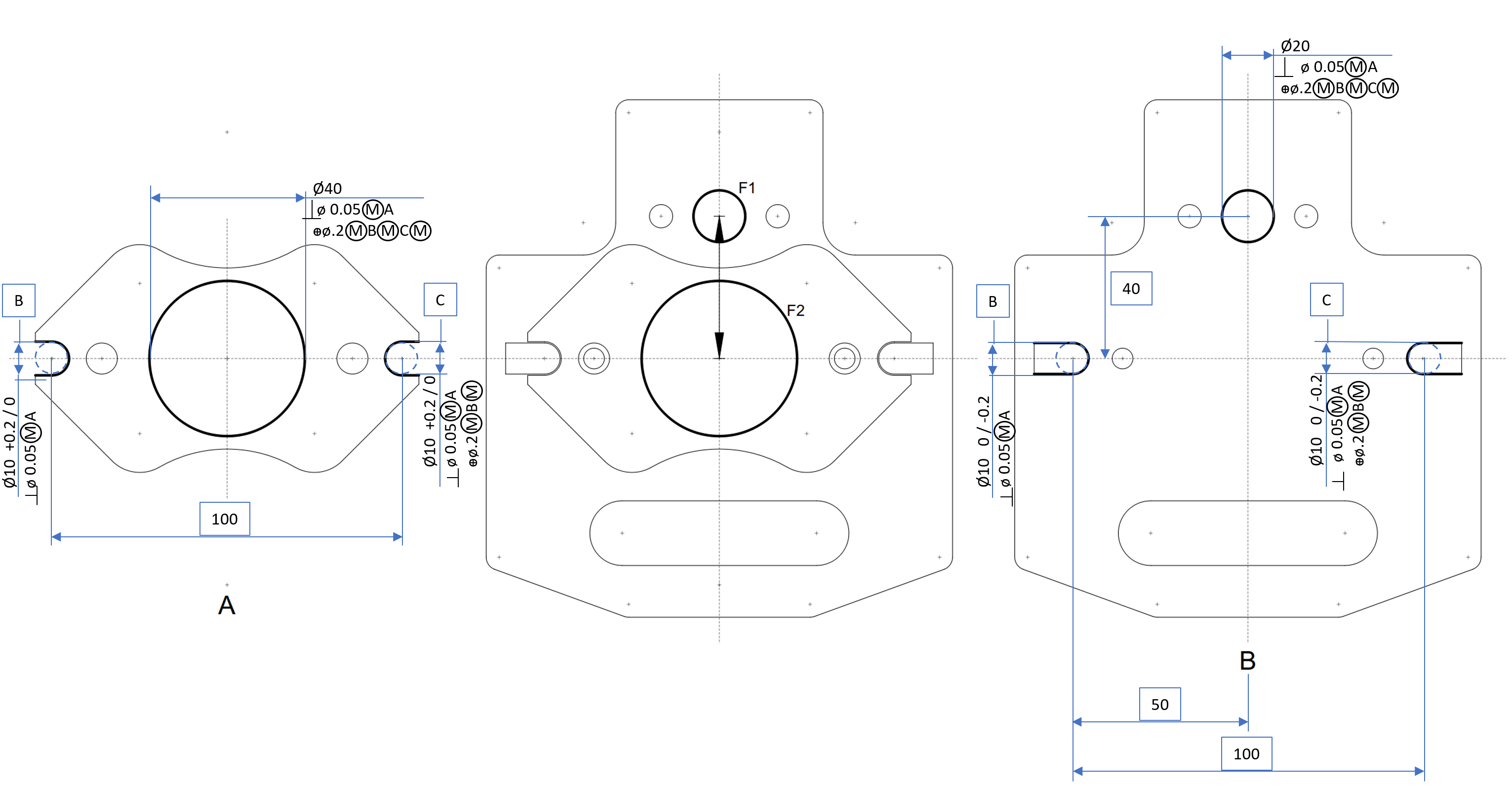
Here is a general idea, with arbitrary dimensions and tolerances. Probably not directly applicable to your situation, you will have to adapt it to the required tolerances and to the available production and measuring equipment. A few things to consider:

  • Depending on the thickness of the parts you might drop the perpendicularity requirements
  • Probably you will have to add shape tolerances
  • Consider changing the positioning features to cylindrical pins and holes. It might simplify both the production and the measurement enter image description here
$\endgroup$
3
  • $\begingroup$ Thanks a lot. This seems like a good starting point. Regarding your last comment, not sure if I understand correctly. Do you mean just using the screw holes (next to the slots, M2) as locating features? The slots are there because I was thinking that using screws for accurate locating features is discouraged. $\endgroup$
    – raisyn
    Commented Nov 23, 2022 at 11:59
  • $\begingroup$ I agree not to use bolts for positioning, unless of course they have an appropriate shaft feature with an exact diameter, e.g. diameter 8 H6. I meant the features for B,C bases on both parts. Now they are basically slots/keys with rounded ends. If they would be cylindrical, they could be checked simply at 3 locations with a caliper, and you would have a very accurate size. But at their current form you would need something more complicated, like a coordinate measuring tool. $\endgroup$
    – Tawhiri
    Commented Nov 23, 2022 at 12:28
  • $\begingroup$ Thanks for clarifying. I checked but unfortunately I cannot add material to the outside of part A. Currently the slot is 2.6mm wide, a hole would have to be even smaller to allow for material on the outside. Another idea would be to remove the slot and make the current mounting hole countersunk, with the countersunk screws pulling the part into the correct location. Then I wouldn't have to use specialized screws (which are quite hard to find in the dimensions that would be required, M2 with a short shoulder). What do you think about that? Or do you think it is better to keep the part as is? $\endgroup$
    – raisyn
    Commented Nov 24, 2022 at 11:10

Your Answer

By clicking “Post Your Answer”, you agree to our terms of service and acknowledge you have read our privacy policy.

Not the answer you're looking for? Browse other questions tagged or ask your own question.