This is part of my on going saga of drafting question with respect to the V2 drawings I am using for practice.
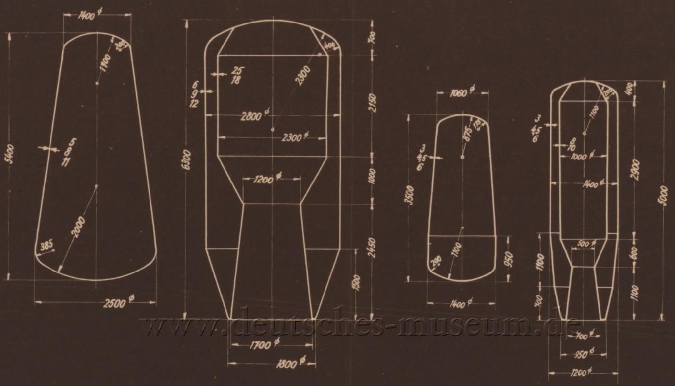
The following drawing is titled "Container Overview". It has left me with 3 questions
- Each part has dimensions pointing at the line which to me seem to indicate wall/material thickness. Either 3 or 2 sets of numbers are given. I was originally thinking tolerance ie 5/8/11 is 8 +/- 3. However that does not explain the 2 number system. ie 25/18 in second part. I did not take this as limits as I am guessing they would not change tolerancing style in the same part. Any ideas what these multiple numbers for the dimension are?
- Continuing with the assumption that the multiple numbers represent wall thickness. When given the various radii for curves, would those dimensions be measured to the inside face, outside face, or mid line usually? I was taking it to the face that the arrow is on. Same with the interior diameters in parts 2 and 4.
- In Part 2 and 4, are they missing a dimension somewhere to position the top of the straight angled lines at the top of the parts?
