1
$\begingroup$

This is part of my on going saga of drafting question with respect to the V2 drawings I am using for practice.

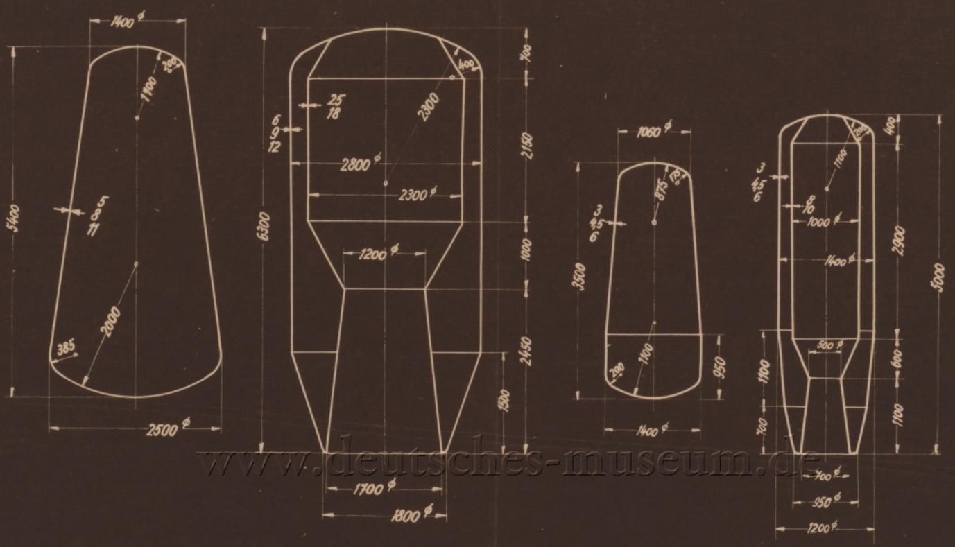
The following drawing is titled "Container Overview". It has left me with 3 questions

Container Overview

  1. Each part has dimensions pointing at the line which to me seem to indicate wall/material thickness. Either 3 or 2 sets of numbers are given. I was originally thinking tolerance ie 5/8/11 is 8 +/- 3. However that does not explain the 2 number system. ie 25/18 in second part. I did not take this as limits as I am guessing they would not change tolerancing style in the same part. Any ideas what these multiple numbers for the dimension are?
  2. Continuing with the assumption that the multiple numbers represent wall thickness. When given the various radii for curves, would those dimensions be measured to the inside face, outside face, or mid line usually? I was taking it to the face that the arrow is on. Same with the interior diameters in parts 2 and 4.
  3. In Part 2 and 4, are they missing a dimension somewhere to position the top of the straight angled lines at the top of the parts?
$\endgroup$
7
  • $\begingroup$ Since I don't read German, what rocket motor is that exactly? The first multistage was the A9/A10, but the dimensions don't match. But the design looks quite similar. $\endgroup$
    – Phil Sweet
    Commented Nov 4, 2021 at 2:30
  • $\begingroup$ @PhilSweet I use Chrome as my browser and it has a built translator that you can tell to convert web pages (not images). Based on what I saw on this page it is my understanding that this is the A4 and A10 fuel tanks. Oxygen and Alcohol if I read right. It is also my understanding that the A4 is the V2. $\endgroup$
    – Forward Ed
    Commented Nov 4, 2021 at 2:43
  • $\begingroup$ I don't think they missed any dimension as they flew into Kent quite often during the war... $\endgroup$
    – Solar Mike
    Commented Nov 4, 2021 at 8:23
  • $\begingroup$ @SolarMike Not denying that at all. However I am guessing based on the sketch I found here, these tanks are for different designs. The tanks in the question's drawing appears to encompass the main engine where the sketch appears to show the fuel tank for the A4 above the engine. I would say these are actually the drawings for the A3 and A5 models and not the A4 based on what I just found. $\endgroup$
    – Forward Ed
    Commented Nov 4, 2021 at 11:53
  • $\begingroup$ The A9 is a modified A4. It was for the winged version of the V2 and the ramjet extended V2. I see it was reported to be bigger than the A4, so it fits now. I was thinking the three numbers were the the thicknesses of the three tank components, the spherical ends, the transition areas, and the shells. $\endgroup$
    – Phil Sweet
    Commented Nov 5, 2021 at 1:58

2 Answers 2

1
$\begingroup$

This is still a bit of a guess, but the combustion chamber was made of two layers of steel with a gap between for the alcohol-water fuel to cool the chamber walls. And in the event of a burn through (a daily occurrence during the peak testing periods), I suppose it would prevent catastrophic explosions. I found that the inner wall dimension was 5 mm. The space and outer wall wasn't specified. I think the 5/8/11 is the thickness of the inner layer, the gap, and the outer layer - so 5 mm inner wall, 3 mm coolant passage, 3 mm outer skin.

see page 409, final paragraph. http://www.raketenspezialisten.de/pdf/jbisdruckvorlage.pdf

Internet is crap at the moment and I can't get an excerpt image.

$\endgroup$
1
  • $\begingroup$ very nice find! $\endgroup$
    – Forward Ed
    Commented Nov 5, 2021 at 14:06
2
$\begingroup$
  1. I haven't seen that form of tolerancing, but your suggestion makes sense, that it might be min / nominal / max ; and min / max when only two numbers.

  2. I would also say same side as arrow. Considerations: Unless I'm missing something, an inside R here would make a direct inspection vs the print impossible on the finished part, because the hollow space between the inner and outer walls would become inaccessible. However the inside R may be more relevant to the tooling, depending on how the part is made. Maybe. You can argue which takes precedence, the ability to inspect directly vs ideal expression of function or manufacturing? It may be unimportant if the tolerances on the R's are bigger than the wall thickness, which may be the case.

  3. Doesn't look like it is controlled??

$\endgroup$
3
  • $\begingroup$ I had not considered the inspection side of things. You answer for Q2 is very eye opening for my thought process. I am used to bridges where we don't deal with tolerances too much on the design side of things. $\endgroup$
    – Forward Ed
    Commented Nov 4, 2021 at 2:19
  • 1
    $\begingroup$ When I was out walking my dog tonight another thought occurred to me about those numbers multiple numbers for Q1. What are your thoughts that it could be thicknesses of the various layers of the wall materials? a composite surface if you will. The only reason I thought of that is these are apparently oxygen and alcohol fuel tanks. $\endgroup$
    – Forward Ed
    Commented Nov 4, 2021 at 2:21
  • $\begingroup$ @Forward Ed - maybe... again I haven't seen this type of tolerancing, and have not worked with relatively complex formed/spun parts like this $\endgroup$
    – Pete W
    Commented Nov 4, 2021 at 19:15

Your Answer

By clicking “Post Your Answer”, you agree to our terms of service and acknowledge you have read our privacy policy.

Not the answer you're looking for? Browse other questions tagged or ask your own question.