1
$\begingroup$

I would like to build a rack for my home with a pull up bar. I'm leaning towards a steel pipe with a diameter of 42.4 mm, but have no idea how to determine what wall thickness is needed so that the pipe doesn't bend under load.

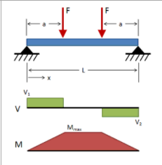
This is a first sketch of the rack. Don't mind the rest of the structure, as most of it is subject to change. The idea is based around the bar, so any change to the bar would change the structure completely. You can think of it as though the bar rests on an idealized structure.

First sketch

The bar is 2190 mm and the unsupported part is 2000 mm long. What I'm wondering is what wall thickness is needed for the bar to not permanently bend?

I found this post discussing what dynamic loads are expected in a similar scenario. One answer says to calculate with 8.9 kN for a person weighing 100 kg with 1 m long arms. I weigh about 70 kg and could travel about 0.60 m (from highest to lowest point). If I do the same calculations I get a load of about 5.5 kN. This scenario would probably not be applicable though. The idea is to use it to build strength rather than power, so a static load of about 1.4 kN (2X bodyweight) might be more suited.

While writing this question I realized that I could also go for a 28 mm steel rod, if it would be cheaper or handle more load for the same price.

Also, I'm thinking it might be best not to fasten the bar in order to reduce stress and only limit its horizontal movement, so it cannot slide/roll out of position. Is that a good idea?

$\endgroup$
8
  • 1
    $\begingroup$ Go to the hardware store and try them out to get a feel for it. Suspend the bar across the aisle. It will take them a few minutes to notice what you're up to. If they're quick the subsequent test may have to be done at another store. Won't you need to stop the bar rotating too when it's in the stand? Fixing it at one end and allowing the other end to float looks like a good idea to me. $\endgroup$
    – Transistor
    Commented Jul 25, 2021 at 17:10
  • 1
    $\begingroup$ I would go to the neighborhood gym and follow the suite. $\endgroup$
    – r13
    Commented Jul 25, 2021 at 17:32
  • $\begingroup$ @Transistor Haha, had it been in my younger years, that would have been an alternative. Also, it seems hard to find a real hardware store where I live, so I will probably have to order it online. Regarding the rotation you would be correct in most cases, but I would like to combine as many training elements as possible in the rack. A rotating bar is more demanding on the grip, so I'll get more out of it for less construction/money. I'm happy as long as it doesn't roll or glide. $\endgroup$
    – Mathphyte
    Commented Jul 25, 2021 at 17:33
  • $\begingroup$ @r17 Yeah, but there are few suits at the gyms in this country =) Also the bars in all the gyms I've been at were not nearly as long. I looked a bit at the high bars they use in gymnastics, but I couldn't find what steel they use. Also, those bars are much longer and have to endure loads that are not comparable, so they would probably be unnecessarily expensive. $\endgroup$
    – Mathphyte
    Commented Jul 25, 2021 at 17:48
  • 1
    $\begingroup$ aren't you going to hit your head on the front beam? $\endgroup$
    – Tiger Guy
    Commented Jul 25, 2021 at 21:03

4 Answers 4

1
$\begingroup$

I will add my answer to the others although the results will not be much different.

The way I see it the following parameters are the most important:

  • The worst case scenario for the bending of the beam:

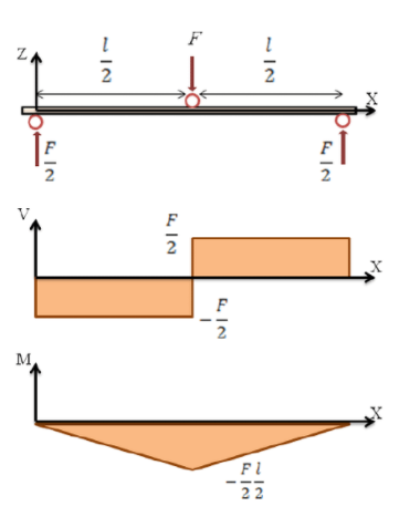
Instead of the open handle (which is a four point bending), I would go for the close handle (which is three point bending). This is a worst loading scenario for a given force.
enter image description here

Figure 1: Three point bending load case with shear forces and bending moments

  • Maximum force:

The idea behind the calculation in the question you are referring is what would happen if someone pulled the chin up and then let go only to hang. IMHO, this is still a valid scenario in your case. Because the intended use is only for strength, that does not preclude an impact load (the equivalent in a car design would be to design cars only for transporting and for crashworthiness). Therefore, I would still go for the 5.5kN (which is BTW approximately 500 kg).

  • Use yield stress instead of uts:

Now this is the hard part, since you probably will be able to get easier steels rod with better strength properties rather than steel pipes. The value would be depended on the surface/heat treatments that the rod has been subjected to, so you need to have an idea. In any case you can take a small value and compare.

comparison of 42.4mm diameter pipe and 28 m steel rod.

In order to compare those to, the most basic comparison is check for their second moments of area. Since you don't know the thickness I will assume its t. Then:

pipe rod 28
pipe 42.4mm with t rod 28[mm]
$$\frac{\pi}{64}(d_p^4 - (d_p-2t)^4)$$ $$\frac{\pi}{64}d_r^4 $$
$$I_p=\frac{\pi}{64}(42.4^4 - (42.4-2t)^4)$$ $$I_r = \frac{\pi}{64}28^4 $$

The structure capable of enduring more bending is the one with the greater I. Therefore, pipe would be better than rod if $$ I_p>I_r$$ $$\frac{\pi}{64}(42.4^4 - (42.4-2t)^4) > \frac{\pi}{64}28^4 $$

After some calculations we obtain that the pipe will be stronger if the thickness is greater that $ t>1.15 [mm]$. (Of course, if you use so small a thickness, then the pipe would probably crumble due to localised bending). So in terms of geometrical resistance, the pipe will probably behave better although I would require it to have a thickness of at least 8[mm] (which I doubt you will have.

Additionally, as I mentioned earlier, it is probable that you will easier find a rod with better material properties.

Calculation for simply supported

Because, I believe the 28[mm] rod is going to be easier on the grip, I will proceed with this calculation and provide the minimum yield stress for the beam.

I assume that the maximum force of F=5.5[kN] is correctly calculated and I will use that as maximum load.

Then the maximum bending for the 3 point bending will be equal for a simply supported beam would be equal to:

$$M=\frac{Fl}{4}= \frac{5.5 [kNm]}{4}= 1.125[kNm]$$

Then maximum stress would be equal to:

$$\sigma = \frac{M}{I_r}\frac{d_r}{2}=\frac{M}{\frac{\pi}{64}d_r^4}\frac{d_r}{2}=\frac{32 M}{\pi d_r^3}$$ $$\sigma = \frac{1125[Nm]}{2.248\cdot 10^{-6} [m^3]}$$ $$\sigma = \frac{1125[N]}{2.248\cdot 10^{-6} [m^2]}$$ $$\sigma = 522 [MPa]$$

This is quite a high strength for yield (although you probably will be able to get a material with those values).

improvement with fixed ends

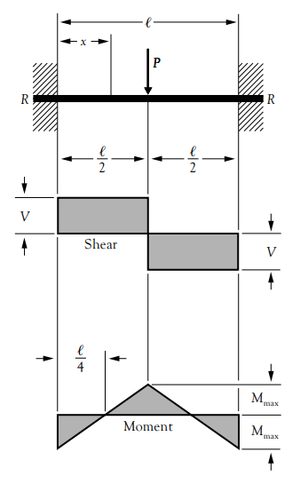
The above calculation is for simply supported beam. However, if you welded the additional 190mm of the beam to the structure, you would have a fixed beam with a concentrated load. In that case the loading condition would improve. I.e.
enter image description here

Figure 2: Beam fixed at both ends (source: awc

In that case the maximum bending moment would be $M_f= \frac{F l}{8} = \frac{M}{2}$. So the bending moment would be only half of the simply supported case.. As such the minimum yield stress would need to be greater or equal to:

$$\sigma_y \ge 261 [MPa]$$

(CAVEATS: there are some asterisks here, regarding with the rigidity of the rest of the structure and stress concentrations, however in general the welded version should perform better). This -hopefully- also answers your final question regarding constraining only horizontally.
$\endgroup$
1
  • 1
    $\begingroup$ Wow, that was quite an answer! I don't know if there is some trouble with the tex-code "$$M=\frac{Fl}{4}= \frac{{5.5 [kNm]}{4}= 1.125[kNm]$$". It seems to be written right but it just appears as code. I read Latex, so I understand it, but I thought I'd point it out if someone else has a similar question and does not understand it. $\endgroup$
    – Mathphyte
    Commented Jul 26, 2021 at 17:27
1
$\begingroup$

Nothing fancy. Just mild steel.

Assuming you go with at least 1"/25mm diameter for ergonomic purposes, go with a wall thickness of 3/16"/5mm which already should be overkill.

At 6ft/2m long and 1"/25mm diameter, I am skeptical if 1/8"/3mm wall thickness will be sufficient. I doubt it would break but it might flex under dynamic load.

And if you go with a solid bar, 1" is definitely way more than enough since that's like an Olympic barbell so unless a 500lbs person is hanging off and doing dynamic movements, you don't need specially treated steel.

EDIT: I just noticed you wanted a very large diameter of 42.4mm. A 5mm wall thickness should be fine there too. 3mm feels uncomfortably thin at that diameter and length due to wall buckling but it would probably work too to be honest. Certainly cheaper. Steel is strong stuff.

I would personally go with gym rings since they are more versatile and works your muscles better than a bar.

$\endgroup$
1
$\begingroup$

Estimating force

You can calculate the section assuming you are as strong as the world record holder for deadlift, which I think is 500kg.

Meaning any maneuver, even acrobatic, that can cause a force imparted by the bar on your hands greater than 500kg will cause you to lose grip and let go of the bar.

Assuming a distance of 40cm between your hands on the bar the loading will be like the diagram below.

The moment

The moment for this loading is $$M= \frac{500kg}{2}\cdot\frac{(200-40)}{2}cm =20000kgcm$$

Let's try a thickness of 5mm.

$$I=\pi/4 (R_{od}^4-R_{id}^4)=96.86cm^4$$

$$\sigma= \frac{My}{I}=\frac{20000kgcm*4.24/2cm}{96.86}=437.74kg< (2500kg/cm)_{allowable}$$ OK.

We have a built-in safety factor of 5.

moment diadram

$\endgroup$
1
  • $\begingroup$ Ah, an answer not in Elvish =P How would the calculation look like with a 28 mm rod and one hand? Also, my calculated velocity is around 3.43 m/s. I read a paper that looked at a small gymnast doing a giant on the high bar. I think he got up to 4.3 kN, so had I been a smidgen more acrobatic the 20000kgcm might have been accurate =) $\endgroup$
    – Mathphyte
    Commented Jul 25, 2021 at 22:08
0
$\begingroup$

Let's do a calculation just for fun.

L = 6.5' P = 250 # M = PL/4 = 250*6.5/4 = 406.3 #-ft

Use A53 or A500 pipe, minimum yield strength fy = 35 ksi (available in local store) Calculate required pipe size stressed to yield:

S = M/Fy = 406.3*12/35000 = 0.14 in^3, for 2" diameter pipe of,

  • standard weight (tw = 0.145", 3.68 mm), S = 0.561, factor of safety = 0.561/0.14 = 4.0

  • Extra strong (tw = 0.218", 5.53 mm), S = .731, factor of safety = 0.731/0.14 = 5.2

I would go for the extra strong pipe, which can support the maximum force of F = 250*5.2 = 1300 # (approx. 590 kgf).

$\endgroup$

Your Answer

By clicking “Post Your Answer”, you agree to our terms of service and acknowledge you have read our privacy policy.

Not the answer you're looking for? Browse other questions tagged or ask your own question.