1
$\begingroup$

I am in the process of developing a robotics design on SolidWorks.

The goal of this design is to tilt a platform using 2 actuators.

My design utilizes 2 indirect actuators that are separately powered and operated to tilt the platform on each end.

Each actuator has a fixed rotational joint at the top, that should rotate along the hinge as it gets pushed up with it's actuator, thus lowering the other side at the same time.

(See MODEL 1 below, which contains a brief 360 and identifies the actuators on my SW model).

Please note the 2 rotational joints at the top of each actuator, and notice that they have full rotational capability at any stage.

However, when I attach a metal plate onto my rotating joints and try to animate my SolidWorks design, it ends up pulling the opposite actuator, and keeps the metal plate level the entire time. It does not move the rotational joint at the top of it's actuator at all. Which does not make any sense because the rotational joint should account for the actuators push.

As the actuator moves up one one side, both joints should rotate by the same angle, and the plate should tilt. However this does not happen at all, both actuators move together, and the plate remains flat.

Can anyone please explain why this is happening and what I can do to fix this issue?

Is this a problem with SolidWorks perhaps?

Any input would be highly appreciated, I can provide more information if needed.

Thank you for your time

(See MODEL 2 below, which contains the problem, a brief 360, and identifies the actuators with the metal plate on my SW model).

$\endgroup$
2
  • $\begingroup$ help.solidworks.com/2016/english/whatsnew/… $\endgroup$ Commented Dec 6, 2020 at 22:34
  • 1
    $\begingroup$ Your model is under constrained - SW has no way of knowing that you don't want both actuators to extend, so it does this because it's easier. SW prioritises translation over rotation when it gets a choice. $\endgroup$ Commented Dec 6, 2020 at 22:35

2 Answers 2

1
$\begingroup$

According to me (if I understand correctly the design and what the goal is) this happens because the distance between the two actuators is fixed. Visualize a parallelogram. It has one degree of freedom, both pairs of sides always pairwise parallel. Your actuators are like two parallel opposing sides of the parallelogram. However, when you flex it, the two actuator sides of the parallelogram come closer together, i.e. the distance between them (represented by a segment that is perpendicular to both sides simultaneously) shortens. In your mechanism, you have eliminated the possibility for the two parallel actuators to get closer to each other. This over-constrains your motion. To fix it, you should allow the two horizontal platforms at the bottom of the actuators to move closer to each other or something like this. For now they are fixed, but try to allow for a horizontal translational motion.

$\endgroup$
0
$\begingroup$

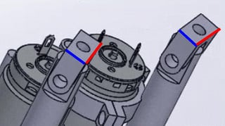
Mate edges in Blue in parallel. Same for edges in Red.

Then you can mate circular plate to actuators.

enter image description here

The why comes more from the idiosyncrasies of how SolidWorks works than how someone visualizes how it works.

Merging the actuators forms a plane, which SolidWorks knows how to manipulate as opposed to three separate objects to manipulate. You could probably get it to work, but the merges would have to be the proper type and in the proper order. Easier to cheat.

$\endgroup$

Your Answer

By clicking “Post Your Answer”, you agree to our terms of service and acknowledge you have read our privacy policy.

Not the answer you're looking for? Browse other questions tagged or ask your own question.