I am, in actuality, a network engineer and not a trained mechanical engineer. It was kind of a hobby of mine until recently, when my boss gave me the opportunity to try my hand at mechanical engineering through CAD design (Autodesk Inventor) about two years ago and I took to it like a duck to water. I have been working in that subject since then.
My problem, however, is that I am unfamiliar with most of the best-practices of mechanical engineering and it has been a "trial by fire" sort of situation. Currently my main problem has to do with the alignment of a chain-drive system used for balancing a counterweight and lifting mechanism.
Details:
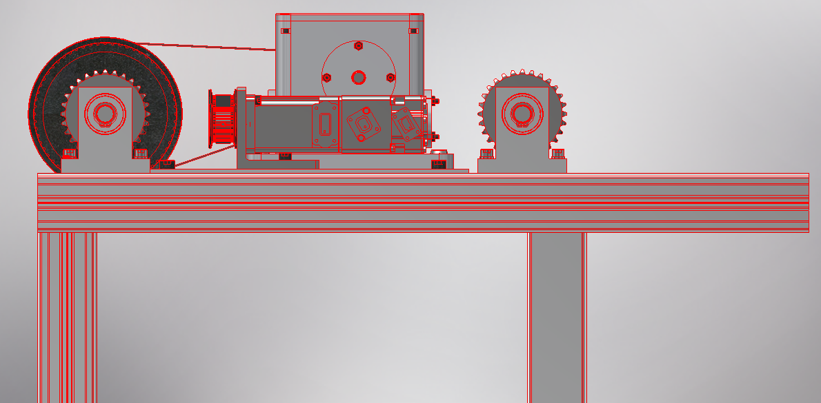
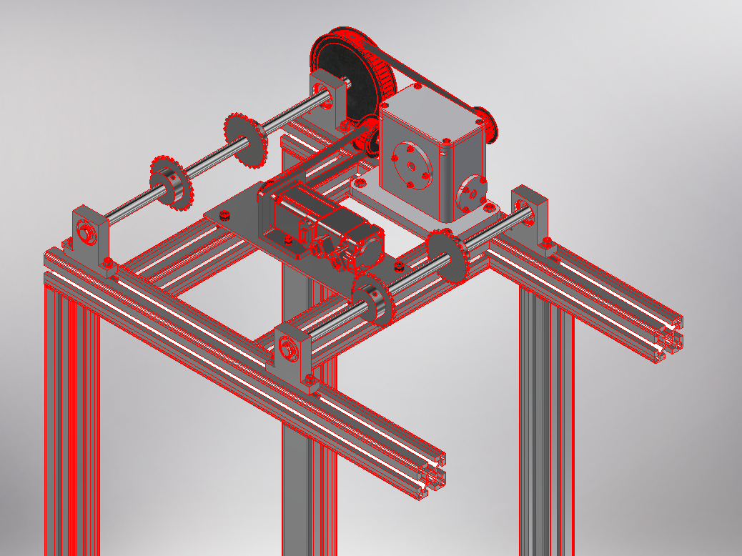
- Horizontal alignment is great in my CAD design, however when I actually order and build out the products, I find it extremely difficult to get the alignments properly set and I end up spending hours fidgeting with the axle and chain sprocket alignment... I am currently using aluminum extrusions (via MISUMI) for the frame design.
In the images below, you will find an example (several components have been redacted due to proprietary design). The images show the main components for operating the lift mechanism. One side houses the sprockets for the Counterweight, the other for the forklift itself. It is controlled by an AC servo motor which attaches to a custom gearbox, and finally to one of the chain axles (the counterweight).
**The design must use these aluminum extrusions, however this makes it very difficult to properly align the bearing housings for the axles, often making everything off-center or skewed, Even when using an accurate measure and square.
Can anyone suggest some improvement points or alternative types of components for mounting the axle/sprockets?

