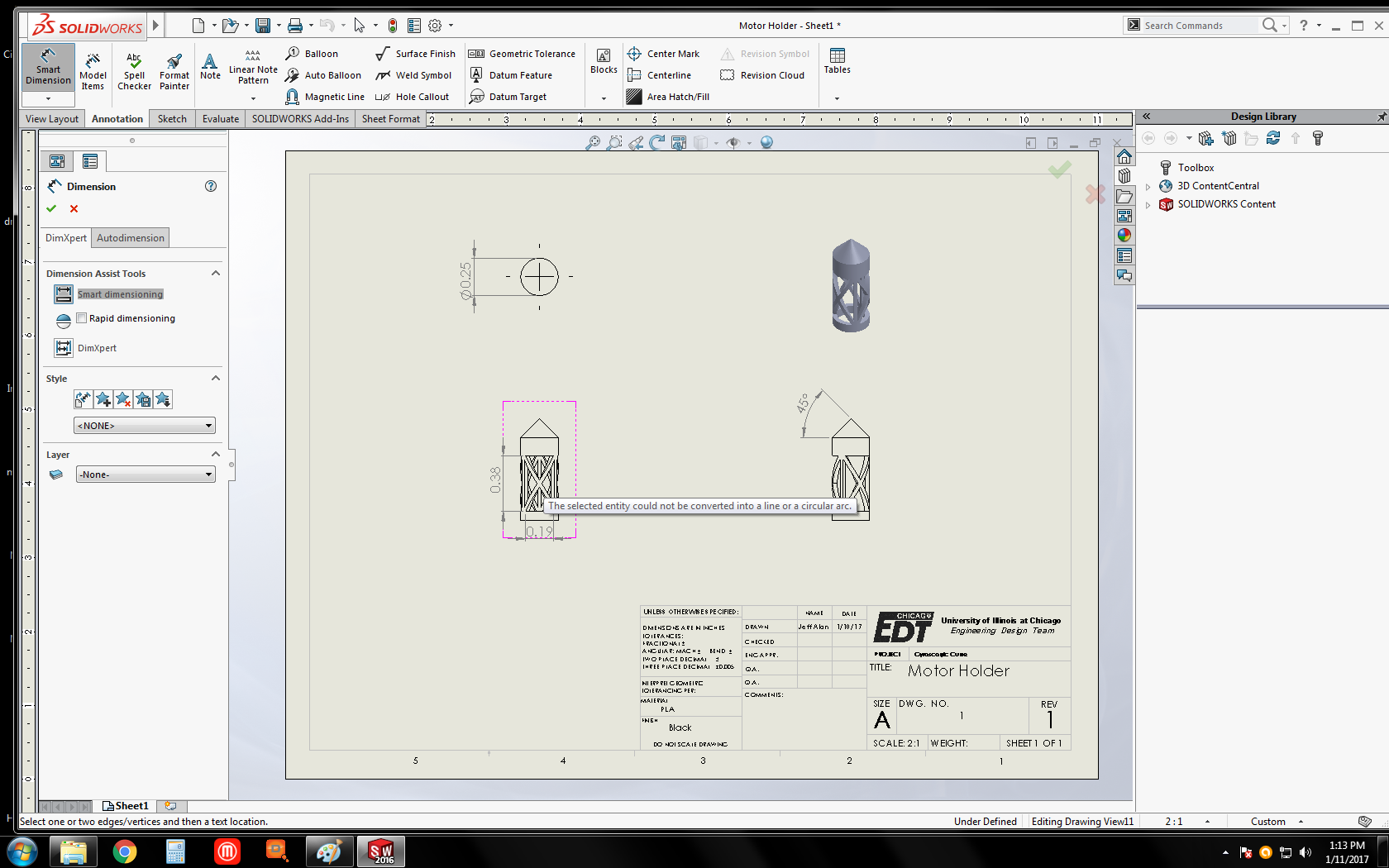
I've been making technical drawings for various parts I've designed. Since these parts were meant to be 3D printed, this is mainly just to have them in my portfolio so I have something to show/talk about at the upcoming career fair (I'm an undergraduate ME student).
I've encountered difficulty with one particular part, which is designed to hold the motor for a perpetually spinning top. Because the motor ran a little hot when turning the rather heavy disc it was attached to, I used the SolidWorks wrap tool to remove portions of the cylindrical casing in order to encourage heat dissipation.
As you can see in the image, SolidWorks is unable to annotate the resulting dimensions, at least not using the basic tools I'm familiar with. So my question is: how would the dimensions of this part be represented on a technical drawing? Relatedly, since it probably determines the answer: by what process could a part like this be machined, if 3D printing was not an option and the arguably unnecessary complexity could not be removed?
