0
$\begingroup$

I have a machine which has belts with three pulleys, one of them is connected to the motors,the one in the middle moves to tighten the belt, and the third is idle pulley. This belt assembly sits on a plate and a strain gauge is attached to the plate. The function of the belts are such that they will pull a fiber by gripping on it and the strain gauge is for measuring the tension in the fiber. The engineer who designed this is no longer available and I don't know how to convert the readings from the strain gauge into tension. I have attached the assembly image, can anyone tell me how to calculate tension in the fiber that is being pulled by the belts from the strain gauge measurements?

Please let me know if additional details are needed.
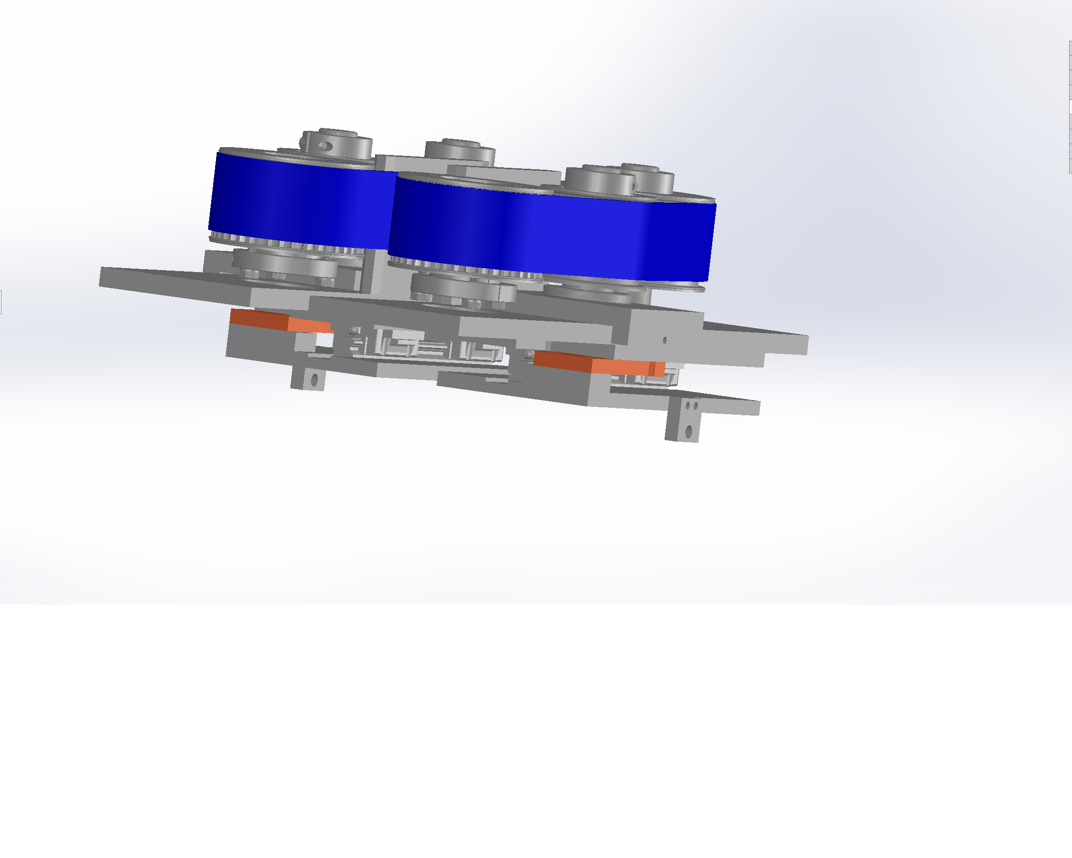
belts in blue and strain gauge in orange

$\endgroup$

2 Answers 2

1
$\begingroup$

Here's how this would work. The tension causes a change in strain. There is a certain calibration factor which tells you how much tension gives how much strain. I think this is what you are looking for (please correct if wrong). For simple shapes like a long circular cylinder, or a long rectangle, you could look up these relation in a textbook. But for something like you've shown it will be much more complicated. There are basically two ways to get this

  • Detailed finite element model (e.g. ANSYS, NASTRAN, Abaqus, etc).
  • Empirical calibration (i.e. apply a known tension to the part, for example using a hydraulic cylinder, and then read off the strain value)

Probably whoever designed this system has already done one of these two things. The easiest thing is just to find that guy and ask him. But if that's not an option then you'll have to it over yourself. Unless you already know how to run finite element models, I don't recommend it. It could take years to get good enough to get an accurate strain value on something like what you've shown. So empirical calibration is probably your best option.

$\endgroup$
0
$\begingroup$

Strain gauges come in a variety of configurations and are sensitive tools. They usually have an excitation voltage and an output voltage and have a certain GF, gauge factor, and are wired as full-bridge, half-bridge, etc.

They need to be calibrated according to their manuals.

They have usually a gain of ~1000 for a 10 Volt excitation.

they communicate to a PC computer via a PCMCIA DAQCard after passing through an SCXI board or the SCXI board sends the signall through the computer parallel port to be processed by their App.

You need to have training and experience of working with them to know the effective range of strain and heat environment, the frequency of data acquisition, etc.

$\endgroup$

Your Answer

By clicking “Post Your Answer”, you agree to our terms of service and acknowledge you have read our privacy policy.

Not the answer you're looking for? Browse other questions tagged or ask your own question.