As mentioned by other answers, when dealing with a statically determinate structure, the stiffness of each element is irrelevant when calculating the bending moment, but a key variable when calculating the deflection. Meanwhile, for statically indeterminate structures, even the calculation of bending moment requires the stiffness.
In simplified terms, this is because in statically determinate structures one can determine how the load is transferred through the structure to the supports without caring about the stiffness itself. In indeterminate structures, however, the stiffness directly impacts how the load is shared by the supports.
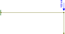
So let's try a variation on your cantilever example:
That's just a cantilever with a force applied at the free end. There's also a dangling vertical beam at the end (which is unsupported at the bottom).
Now, I don't need to know anything about the stiffness of each of those beam segments to determine how the load will be divided between them. We trivially know that dangling beam won't do anything, and all the load will be resisted by the cantilever. After all, that dangling beam might be infinitely stiff, but it's a dead end.
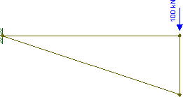
Now imagine you get the thinnest possible steel wire and use it to connect the bottom of the dangling beam to the support (with fixed connections, not pinned). Your structure diagram then becomes something like this:
Now, given how weak that new diagonal "beam" is (just a tiny wire), we can probably approximate its stiffness as equal to zero (especially when compared to the stiffness of an actual steel beam). Which basically means we can pretend the diagonal doesn't exist. Therefore, the structure will actually behave exactly as it did in the original case: the entire load will be resisted by the horizontal beam.
So, that was easy enough.
But now imagine the diagonal and horizontal members were reversed: the diagonal is the steel beam and the horizontal is just a pitiful wire. In this case, we can obviously state that the load will travel down the vertical (previously dangling) beam and then up the diagonal towards the support, with the tiny wire not really doing much of anything.
But what if both the horizontal and diagonal beams are steel beams, and therefore both contribute to resisting the load? Well, then we can't trivially figure this out anymore.1
And that's why calculating the shear force and bending moment of statically indeterminate structures depends on the elements' stiffness: each element's stiffness defines how much load it must support. And the proportion of the load going to each element is directly proportional to its stiffness: the stiffer the beam (as compared to others sharing the load), the more load it must support.
1 This is a bit off-topic, so putting this as a footnote. To actually calculate this case, you need to use compatibility equations which effectively guarantee that the diagonal's deflection at the free end is equal to the horizontal's deflection at its free end plus the vertical's compressive deflection. Basically equations which guarantee that everyone agrees where (and at which angle of rotation) the nodes end up in the structure's deflected shape.

