0
$\begingroup$

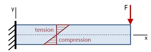
Load scenario

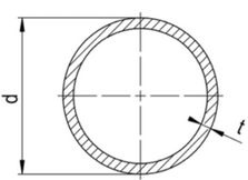
Cross section of beam

It is thin walled because roughly d=200mm and t=6mm of a carbon fiber wrapped tube.

The question is, if the bending stress $\sigma$ over the cross-section (in y-direction) is linear or not.

It is clear to me that the bending moment over the cross-section must be linear (as depicted in the top picture), but because of the relation:

$\sigma_{b} = \frac{M_{b}}{W_{b}}$ and in this case $W_{b} = \frac{I_{xx}}{d/2}$

i am unsure if the bending stress would also be linear because the second moment of area $I_{xx}$ is defined as $I_{xx}=\int y^2 \, dA$ which surely isn't linear for the given thin walled tube cross-section, right?

If my train of thought is correct, then what would the form of the bending stress diagram over the cross-section?

Context: I try to measure the bending stresses of a CFRP tube without knowing the position of the main axis of the load. In turn, I will be using 3 strain gauges around the outside of the tube spaced 120° apart. But I need to know the distribution of the bending stresses across the cross-section to see if and how I can calculate the position and amplitude of maximum bending stress from these three measurements.
$\endgroup$

2 Answers 2

0
$\begingroup$

The stress diagram across the x-section is linear.

$\sigma = \dfrac{My}{I}$ 

Note that the equation for "Moment of Inertia for Circular Cross-Section" is I=πd4/64, and a pipe's moment of area is calculated similarly given by I=π(D4-d4)/64, where D=Pipe OD and d=Pipe ID.

$\endgroup$
2
  • $\begingroup$ But can we just set the moment of inertia as constant here? Thinking about it simplified in a tension force on the top half of the circle, a infinitesimal area on the very top would be smaller than half way down wouldn't it? In turn making the stress $\sigma = \frac{F}{A}$ non-linear. On a rectangular beam, as all the school-book examples are, this wouldn't be a problem. $\endgroup$
    – Xenox
    Commented Jan 4 at 23:01
  • $\begingroup$ Other than "y", there is no variable in this equation. $\endgroup$
    – r13
    Commented Jan 4 at 23:46
0
$\begingroup$

Just to add on to what r13 mentioned, with your tests, I am sure you will find that the strain and calculated stresses vary with location on the outer and inner skin of the tube. If you consider the formula at y=0, what will the stress be? I think you see where I am going as your post has an excellent diagram showcasing this point.

Further, you can pick up any Machinery's Handbook and find the formula for stress at any point: s=W*(l-x)/Z.

$\endgroup$

Your Answer

By clicking “Post Your Answer”, you agree to our terms of service and acknowledge you have read our privacy policy.

Not the answer you're looking for? Browse other questions tagged or ask your own question.