0
$\begingroup$

I’m trying to calculate the beam deflection for an inclined beam. It’s only connected to floors (and not walls). The beam is a monorail, and I want to test different shapes (tubes and I-beams).

Plenty of online calculators can help, but I noticed none have the option where each support can be set to a different height.

I assume raising one support higher than the other will result in a different amount of deflection (probably not a whole lot, nevertheless).

So my question is, what is this type of calculation called? How would this calculation be done?

Many thanks.

// UPDATE 1

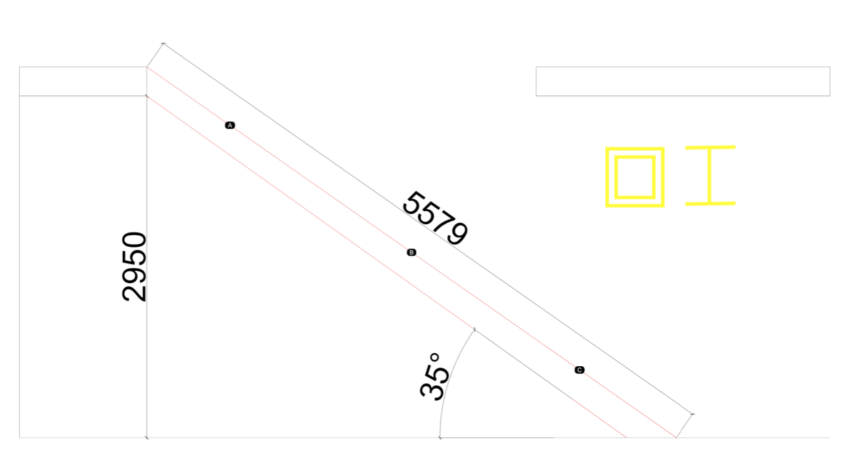
I made a schematic of the beam (in red)/situation. In yellow the 2 type of beams I want to calculate the deflection for. For example, I marked the point load as A, B, and C.

enter image description here

$\endgroup$
11
  • $\begingroup$ Sorry, I still don't understand what is the "pin" in this setup, do you mean the " steps or "rungs" as shown dots in your picture? Please identify the "pin" and show the look of the stair with one pin higher than the others. Thanks. $\endgroup$
    – r13
    Commented Sep 15, 2021 at 14:54
  • $\begingroup$ @r13 sorry, the "pins" are the outer points of the bean. So pin-1 is where the beam touches the floor, and pin2 is where it touches the second floor (follow the line straight up that says 2950). Measurements are metric. $\endgroup$
    – Roger
    Commented Sep 15, 2021 at 16:11
  • $\begingroup$ See the added section - "Verification" near the end of my answer. $\endgroup$
    – r13
    Commented Sep 15, 2021 at 20:37
  • $\begingroup$ By the way, the verbiage for the "pin" is a "pin support" or "support pin". However, you can address the beam is **supported" by pins at the ends, then people will understand what you mean and would not give it a wild guess, such as the "pin at the bowling alley" :) $\endgroup$
    – r13
    Commented Sep 15, 2021 at 21:20
  • $\begingroup$ @r13 thanks for the clarification! $\endgroup$
    – Roger
    Commented Sep 17, 2021 at 7:10

2 Answers 2

0
$\begingroup$

Let's say you have a 7" riser to 12" tread so you have an angle of 30 degrees.

We break the load on the stringer into its 2 components: perpendicular to the stringer (beam) and normal to it.

Let's say your beam length laid flat is 12ft. and let's say the live load is 100lbsft

So we have to apply $$ 100*cos30 = 0.866*100=86.6 lbs.ft $$

And your normal force to the stinger is $$100*sin 30 =50lbs.ft$$

We calculate for a flat beam with L=12ft and w=86.6lbs.ft and a uniformly applied normal load of 50lbs.ft.

This means on the lower point of the stringer we have 12* 50= 600lbs force but on the top, we have zero normal force. which is not a big deal, Usually the governing factor is the moment.

And the approximate deflection is calculated as $$\frac{5\omega L^4}{384EI}*cos30$$

We know this depends on what you mean by the deflection of an inclined beam, but it is a good estimate.

Or one could calculate the deflection for a beam of L= 0.866*12 and apply 100lbs load and calculate the deflection.

$\endgroup$
2
  • $\begingroup$ Second paragraph...Perpendicular and Normal is the same thing. Or did I miss something? $\endgroup$
    – Forward Ed
    Commented Feb 9, 2023 at 22:37
  • $\begingroup$ @ForwardEd, no, by perpendicular i mean transverse, if we call the long axis of the stringer X, axis, the perpendicular would be 90 degrees to X. $\endgroup$
    – kamran
    Commented Feb 10, 2023 at 0:45
0
$\begingroup$

If I understand correctly, the beam is a single structural shape simply supported on both ends by the floors that are considered pin-supports. One of these supports can be moved higher while the other holding constant, as thus, the question is - will the deflection change?

The answer is "Yes", because the physical beam length (along the slope) has changed, and the magnitude of deflection is direct proportional to the beam length.

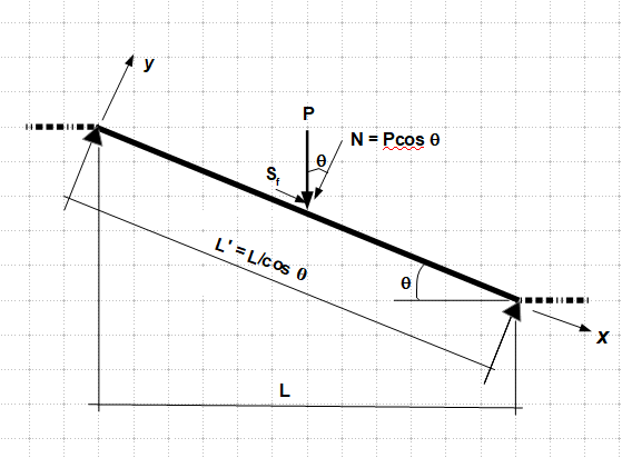
The calculation method is identical to the ususl beam deflection calculation, however, the calculation shall be performed on the beam along the inclined axis, that is, the length of the beam to be input into the equation equals the horizontal span length (between supports) divided by the cosine of the angle of the incline ($L' = L/cos \theta$; Also, the gravity load needs to break into component forces -force acting normal to the beam ($N$), and force acting along the beam ($S$), note that the latter force is ignored in general practice, so the force to be input to the equation equals $N = Pcos \theta$.

Hope this answers your question.

Verification:

In order to evaluate the deflection of an inclined beam, we need to work on its own (local) coordinate system ($x$, $y$), so we need to break the force into the components - normal force ($N$), and thrust ($S_f$), and to calculate the effective length of the inclined beam ($L'). These steps are shown in the sketch below.

(*) Note, for simplicity, let's assume only the normal force causes the beam to deflect. To be exact, the thrust will increase the magnitude of the deflection to a small extent, which is usually ignored in practice, except that deflection caused by the normal force is rather large.

The calculation of the deflection is identical to the beam in horzontal:

$\Delta = \dfrac{Pcos \theta (L/cos \theta)^3}{48EI} = \dfrac {PL^3}{48EI cos^2 \theta}$
enter image description here

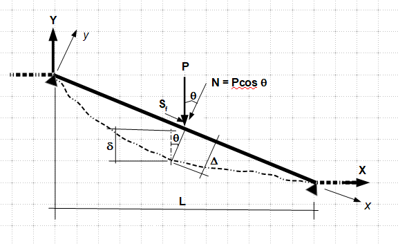
Finally, the true deflection measured in the Global Coordinate system ($X$, $Y$) is:

$\delta = \Delta cos \theta = \dfrac {PL^3}{48EI cos^2 \theta} cos \theta = \dfrac {PL^3}{48EI cos \theta}$

Now let's set $\theta = 0$, which is the condition of a horizontal beam:

$\delta = \dfrac {PL^3}{48EI cos 90^o} = \dfrac {PL^3}{48EI}$. The exact form of the deflection equation for a horizontal beam, thus, we recognize the influence of the angle of the incline.
enter image description here

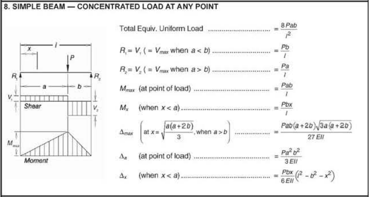
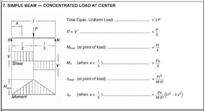
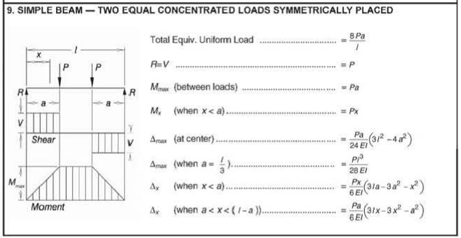
For your case with 3 loads and the equation of the deflection could be unknown to you, you may utilize the tables below to calculate the deflection for each loading case shown, then combine the results at the points of interest through the method of "superposition".
enter image description hereenter image description here

enter image description here

$\endgroup$
3
  • $\begingroup$ Thank you for the help (also for @kamran)!, I updated the question since I felt it was not fully clear. $\endgroup$
    – Roger
    Commented Sep 15, 2021 at 11:58
  • $\begingroup$ It is much better to not decompose the forces (which we haven't been told about). If you have a roof with a snow load based on horizontal pounds per square foot, the total distributed load on the roof will be the same regardless of pitch, so working in the horizontal and vertical axes is much more convenient. And if you have the same total load distributed over a span, it doesn't matter what the pitch is because the increase in second moment of area in the vertical plane will compensate for the increase in length. Rafters are sized the same regardless of roof pitch. All you need is the span. $\endgroup$
    – Phil Sweet
    Commented Oct 8, 2023 at 13:22
  • $\begingroup$ If only for your own satisfaction, please rework without the decomposition, and test using different load cases to see what happens. Nicely presented answer, but the conclusion is basically wrong for many common applications, and that needs to be explained. $\endgroup$
    – Phil Sweet
    Commented Oct 8, 2023 at 13:25

Your Answer

By clicking “Post Your Answer”, you agree to our terms of service and acknowledge you have read our privacy policy.

Not the answer you're looking for? Browse other questions tagged or ask your own question.