2
$\begingroup$

I'm putting together a ceiling-mounted clothes rack. The rack is raised and lowered with rope and pulleys.

If the rack is raised under full load and accidentally released, then the system could be damaged and it might pose a danger to anyone near it. I'd like some type of device that will control the rate of descent, but I'm not an engineer and I'm not familiar enough with the correct terminology for parts to google for a solution.

I want the braking force to be proportional to the velocity of the descent, so some analogy of a dashpot I imagine is the answer. It should descend at (approximately) the same velocity no matter the amount of weight on the load.

I found some ideas online but not exactly what I want. Some solutions will stop the rope from moving if it accelerates too quickly. I don't want the load to stop moving, just be limited to some set value.

I had an idea where I have a ring around the rope at some point that exerts minimal friction to the rope. The ring is attached to a pivot. If the rope moves through the ring too quickly, this exerts a force on the ring which would rotate around the pivot point. The ring would then exert a greater amount of friction on the rope, thus slowing the load. I don't know if this would work. I think it would be tricky to calibrate and I'm not sure if it would have the correct effect. I don't think the friction between the rope and the ring increases with the speed of the rope.

Another idea would be to at some point have the rope move through a pulley and the pulley has an inefficient propeller attached to it. As the speed increases, so the does the air resistance thus slowing the descent. But that sounds cumbersome.

Ideally, I'd like the rack to descend at a constant speed that's independent of the weight of the rack at that time, yet ascend unimpeded as fast as the user can pull it back up.

Can someone point me in the direction of the simplest mechanism that would solve this?
$\endgroup$
7
  • $\begingroup$ sensor and feedback are terms associated with control. how is the clothesline raised in the first place? If it's manually and there are no electronics involved, a rotary damper might be able to slow a pulley down. if the line is designed to slip on the pulley, you may be looking for a brake (such as your ring) instead. To decouple up and down, a term to seek is ratchet $\endgroup$
    – Abel
    Commented May 31, 2021 at 19:00
  • $\begingroup$ Get a manual chain hoist. Garage hobbyists use them. $\endgroup$
    – user33233
    Commented May 31, 2021 at 19:07
  • $\begingroup$ use a drum winch $\endgroup$
    – jsotola
    Commented May 31, 2021 at 19:11
  • 2
    $\begingroup$ The operation you are describing is the same as an autobelay used for rock climbing - perhaps look into how they work? $\endgroup$ Commented May 31, 2021 at 20:33
  • 1
    $\begingroup$ @JonathanRSwift This sounds right. I learned that these are an example of rotary dampers, like Abel suggested. This pointed me in the right direction. Thanks! $\endgroup$ Commented Jun 1, 2021 at 20:04

3 Answers 3

3
$\begingroup$

Another idea would be to at some point have the rope move through a pulley and the pulley has an inefficient propeller attached to it. As the speed increases, so the does the air resistance thus slowing the descent. But that sounds cumbersome.

This method has merit. The axle of the propeller should be large enough diameter and should have a surface rough enough to prevent slipping. A single wrap of the rope around the axle provides the drag to the system. As you've noted, as the speed increases, the drag increases. Years ago, I saw a movie in which the characters escaped by jumping from a roof, attached to cable which spun a series of flat blades. The flat blades provide higher air resistance. You'd want to avoid the much lower drag of a propeller for that reason. The movie is Green Ice (1981) and the specific segment can be viewed on YouTube.

Additionally, one need not restrict the system to air as the fluid involved. Oil, water, any viscous liquid in which the spinning mass is immersed would provide for a higher level of friction, resulting in a smaller assembly.

The design should be a semi-closed system. Consider a shop vacuum, which has a spinning impeller inside a chamber. Air flowing through the vacuum creates a certain level of noise. When one blocks the intake, the motor noise (and speed) increases, as the impeller is now spinning in a closed system in which the drag is reduced.

For a liquid equivalent, the spinning paddles have to move the fluid from the intake to the output, but that could be as simple as a tank with sufficient space at the top to take in the ejected liquid.

Speed control can be accomplished by a valve on the input pipe or the output pipe.

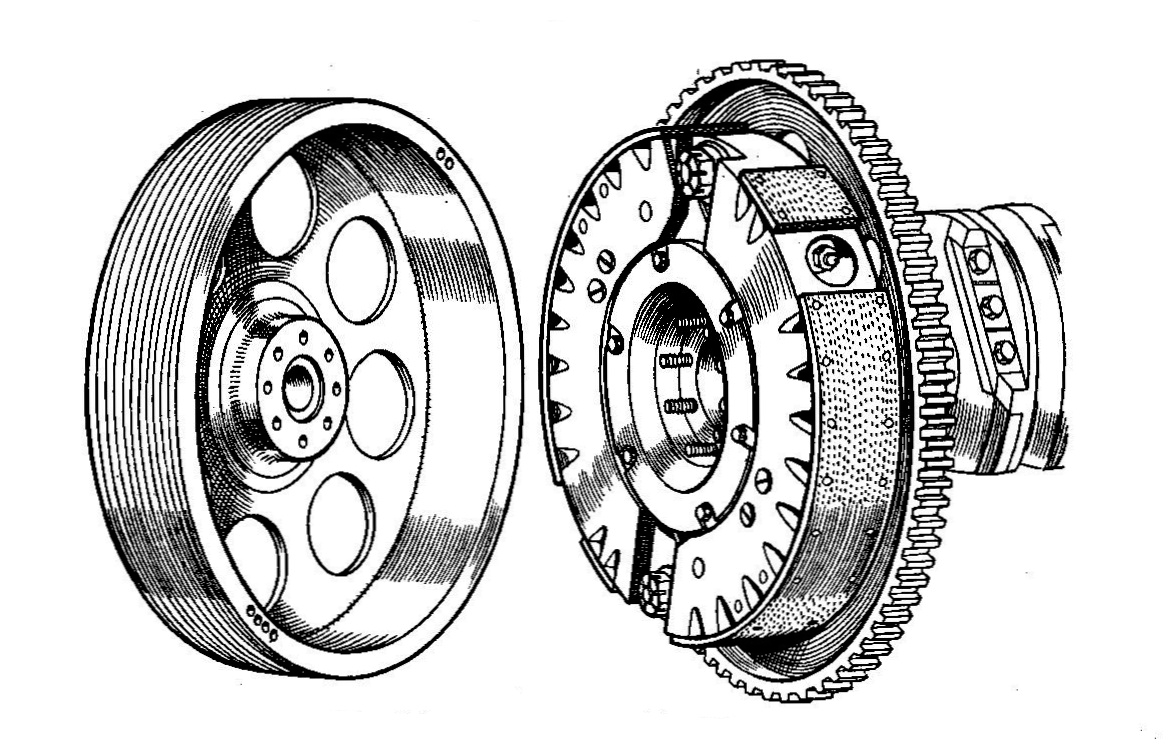
Another method is analogous to the centrifugal clutch on a go-cart engine or ICE chain saw. As the speed of rotation increases, the arms containing the equivalent of brake material are thrown outward, contacting the metal cylinder enclosing them. In an engine, the metal cylinder is the output drive train. In your rack assembly, the metal cylinder is affixed to the frame. These designs can be quite compact, about the size of a coffee mug and manage as much as five horsepower / 3.7 kilowatts.

centrifugal clutch of the 30s

Clutch image from linked web page.

$\endgroup$
3
$\begingroup$

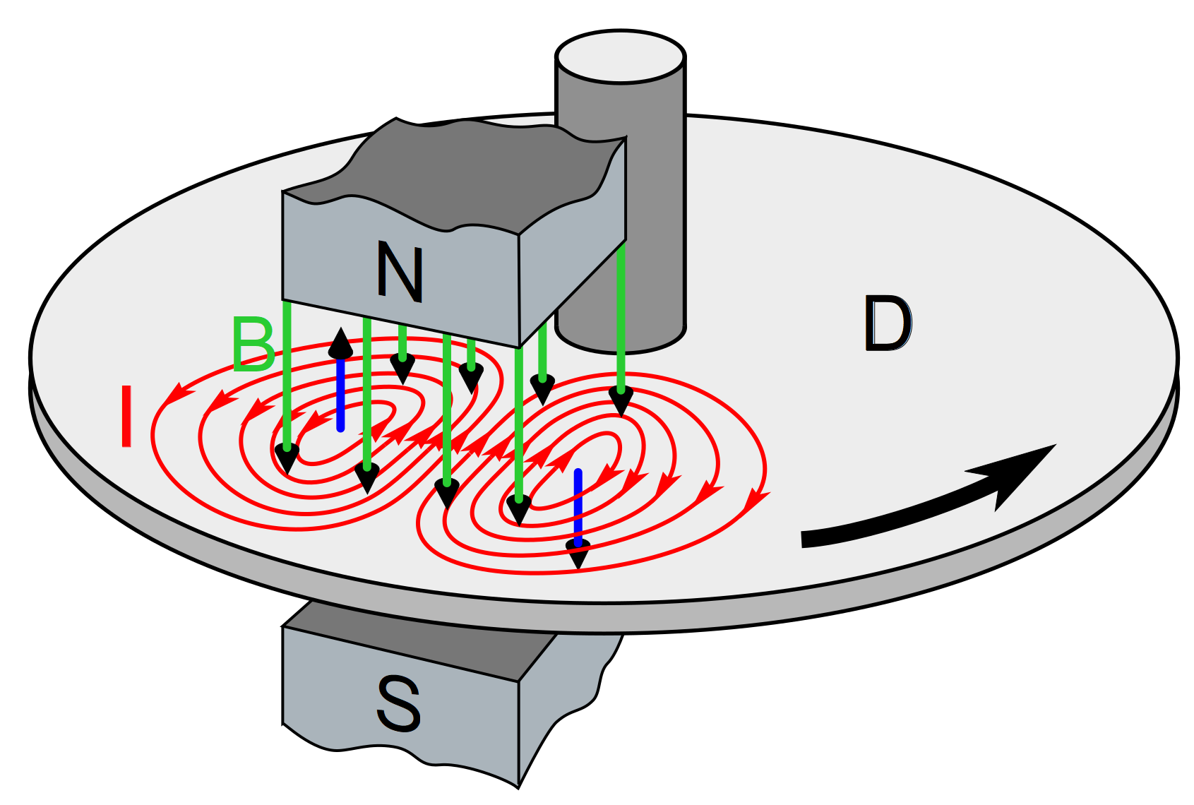
An eddy current brake is easy to build and might suit this purpose. Simply attach a largish aluminum disk to the pulley and place some powerful fixed magnets close to it near the outside where the disk spins fastest. This will produce a smooth braking force that increases with the square of the rotational speed.

https://en.wikipedia.org/wiki/Eddy_current_brake

enter image description here

$\endgroup$
1
$\begingroup$

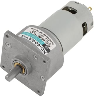
Use a brushed DC gear motor and short the leads with a diode. Make sure that the gearbox is NOT a worm drive type or it will not back drive.

This 150 RPM gearmotor is $54 on amazon and should be close to what you need. There are multiple gear ratios in the drop down to select from. 12v or 24v doesn't matter. To get better than just my blind guess I recommend posting a fresh question with the mass range of the clothes, pulley configuration, rope diameter, and desired velocity.
        enter image description here

Then for your initial test just connect the two leads of the motor to each other; shorting them. This will provide maximum breaking. If the system descends too slow, you can add a resistor (or multiple series resistors) in line to increase the speed. Again, you can experiment or post back a fresh question when you get to that point.

And the best part of this option is that you can use a $0.50 diode across the leads to cause it to only break in one direction; no fancy clutch system required. In the down direction electricity generated by the motor/generator short circuits and turns the motion into heat inside the motor. In the up direction the diode blocks the flow of electricity and does not dissipate any energy. It will still have some resistance in the lifting direction due to the friction in the gear box, but should be minimal.

Both the fluid friction breaking and eddy current breaking ideas posted are also potentially good solutions. Building on those a bit:

Fluid Friction Breaking
To keep the fan reasonably sized, you will need a gear reducer same as above (again non-wormdrive); in this case to increase the speed of the fan and dissipate more energy. It takes a bit of engineering and some details about your system to get this in range. If you go this route I would recommend posting a new question with the mass range of the clothes, pulley configuration, and desired velocity. To go up quickly you will need a one-way clutch. They are not too expensive, but you will probably need CAD & 3Dprinter or a machinist to mount it.

Magnetic Breaking
Neodymium magnets and an aluminum disk will work, but will take a fair amount of experimentation. To operate without a gearbox, I would ball park guess your disk will probably need to be on the order of 12" in diameter with ~10cm^3 volume of neodymium magnets. Magnets need to be as close to the surface of the disk as possible. For the reverse direction you will again need a one way clutch, or could have a mechanism to move the magnets an inch or so away from the disk.

$\endgroup$

Your Answer

By clicking “Post Your Answer”, you agree to our terms of service and acknowledge you have read our privacy policy.

Not the answer you're looking for? Browse other questions tagged or ask your own question.