My background is in Environmental Science, although I have recently been taught in the basics for energy engineering especially for solar panels.
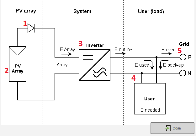
I'm currently using PVsyst to build solar panels on a given building at a given location. However, I'm finding it difficult to explain and understand this diagram with my limited circuit knowledge.
Can someone offer a detailed explanation of the components along with what they represent in the network and what the entire picture means? I know that 1. represents a diode, and it looks to me that 2. represents a European-resistor, I partially know this because of basic practice in LtSpice.
