0
$\begingroup$

The problem is the following. I have to control a spaceship (assuming no gravity, no mass, no friction / no external forces). In other words, the first equation in this question leads to $0 = 0$. My goal is to reach a position for a given acceleration (i.e. throttle).

The movement equation (assuming a constant acceleration) is the following: $x(t) = 0.5 * a * t^2 + v_0 * t + x_0$ where $v_0$ is the initial velocity and $x_0$ the initial position ($x_0 = 0$). Finally, I get $a = (goal - t*V_0) / t^2$ where $goal= target - traveled_distance$

I put this equation in my system. There is a sensor to measure the velocity. Each time the velocity is measure, I can send a new acceleration command.

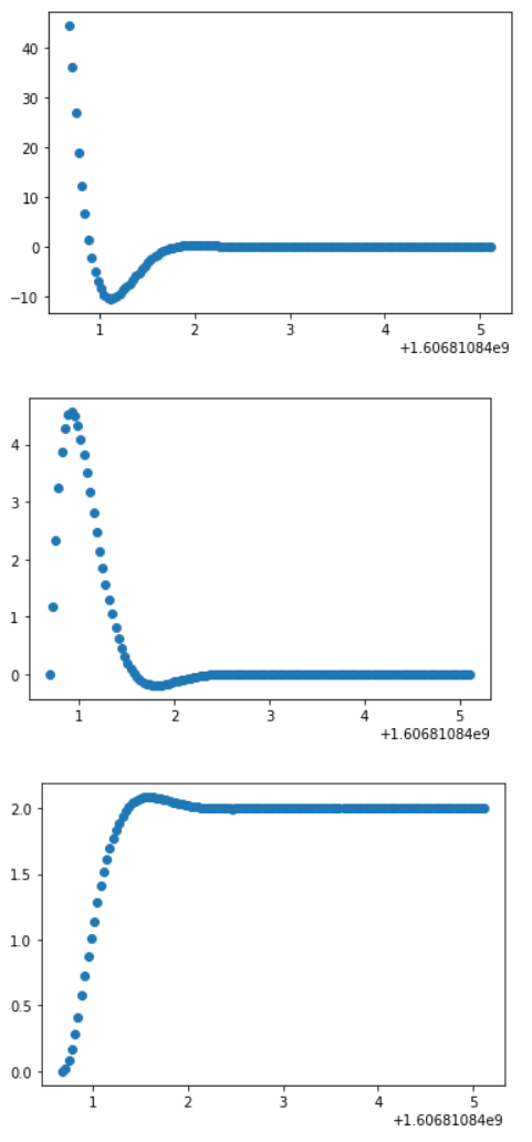
I got the following plots (the first one is the acceleration, the second one the velocity, and the last one the trajectory)

enter image description here

On the last plot, we can clearly identify the response of a second order system. I also observed that increasing $t$ reduces the overshoot (so I guess that $t$ is acting like a proportional gain).

My question is what would be the corresponding transfer function? I tried to identify it with a second order differential equation but did not get any convincing results.
$\endgroup$
1
  • 1
    $\begingroup$ I fail to understand the meaning of a system discussing acceleration with no mass. $\endgroup$ Commented Jan 25, 2023 at 20:57

2 Answers 2

0
$\begingroup$

Ignoring your acceleration control rule (which I would not do this way) your transferfunction looks like this: $$H(s) = \frac{1}{s^2}$$ where the input is the acceleration, the output is the position. Since you measure the velocity, the transferfunction changes to $$H(s) = \frac{1}{s}$$ As for your control goal, you assume the acceleration is constant, however the plot shows otherwise. Other than that, its based upon the logic that within some time interval $t$, assuming constant velocity, the error changes to something. Increasing this $t$ allows it to respond less aggressive, thus less overshoot. I on the other hand advice to simply close the loop and use a PD controller to control the system: $$T(s) = \frac{\frac{P+Ds}{s^2}}{1+\frac{P+Ds}{s^2}} = \frac{P+Ds}{s^2+P+Ds}$$ Where the error equals $Goal - x \approx Goal -(x_{prev} + v \cdot Ts)$ where $v$ is the measured velocity, $Ts$ the sampling rate and $x_{prev}$ the sum of all earlier measured $v\cdot Ts$ and $x0$. Do note that using an discrete integration like this might result in large offsets due to integrating noise (introducing drift).

$\endgroup$
0
$\begingroup$

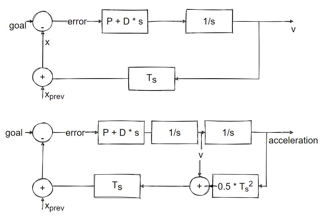
How would look like the block diagram then? I can only think about that:

enter image description here

You formula suggests an unit gain return though.

$\endgroup$
1
  • $\begingroup$ Integrating velocity does not yield acceleration, its the other way around ;). The output of the controller is an acceleration (usually a force, but we omit masses here). This means that your top diagram looks the most accurate. Estimating the position this manner should require a delay to ensure xprev is also updated each time step. If this is implemented in simulink, you should set the simulation solver to a constant time step to make it work. If not, you'd better off replacing this part with a 1/s block. $\endgroup$
    – Petrus1904
    Commented Dec 6, 2020 at 13:49

Your Answer

By clicking “Post Your Answer”, you agree to our terms of service and acknowledge you have read our privacy policy.

Not the answer you're looking for? Browse other questions tagged or ask your own question.