3
$\begingroup$

I am working on upgrading a research project on wind energy. They are trying to measure the performance of wind blade designs in a small wind tunnel (i.e. their models are relatively small).

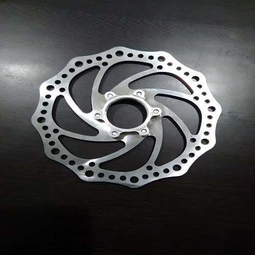
What they were doing was measure the torque generated by the wind by mounting on the axis of the wind blade a bicycle discbrake and engaging it. (They have gone through many mechanical iterations)

enter image description here

Currently they are using a servo motor to pull a bike cable that activates the clamps. What they do is: blade is accelerated, and then the brakes are applied and bring the blade to a halt. While the blase is slowing down, they are measuring the torque and rpm. In order to maintain a constant force on the clamp they are using a spring to maintain a constant tension of the bike cable.

I am upgrading the measurement software side, and two of the wishlist feature requests were :

  • to control the system to apply enough clamping force that will maintain the number or rpms. (apparently they had tried that in the past with a PID but it did not work out).
  • to maintain a constant torque on the design (i.e. clamping force on the discbrake).

When I saw the system I could see the following issues:

  • given the discbrake design, the available travel between engaging and free running is very small (a few hundred microns). That makes the system the system very non linear and very difficult to control (in a few microns you go from 0 to max braking power - even with a lever).
  • there is a lot of play on the discbrake (its wobbly) - due to the mounting of the shaft- , however because the shaft is spinning at 3000 to 10000 rpm it tends to self align.

Overall, I wasn't hopeful that I could achieve the level of control with their current system.

So my question (inspired while I was reading this question) is what mechanisms can I look into to apply a controllable clamping force (or equivalenly clamping torque) on a 3[mm] spinning shaft which is rotating at 3000-10000 rpm?
$\endgroup$
1
  • $\begingroup$ NB that hydraulic disk brakes are 'known' (by cyclists) to have better modulation than cable brakes. Maybe use hydraulic brakes and use the servo to move the lever. Even with a cable system you should be driving the lever not the cable itself as you implied $\endgroup$ Commented Oct 3, 2020 at 8:06

3 Answers 3

3
$\begingroup$

The position of the calipers isn't what you are adjusting, it's the pressure you exert on them.

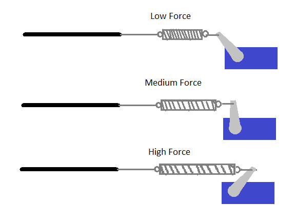
Assuming the system is relatively slow (break force ramps up and down ~1 second), then a spring which is tensioned by a servo should work fine for this.

enter image description here

If the spring is stretched further, the breaking force will be increased. Notice that even though the cable is barely moving, the force applied to it is changing.

You stated that PID control of this servo for constant torque or rpms "didn't work", but why didn't it work? Was the servo too slow to react? Was the control loop unstable? I think we need more specifics.

$\endgroup$
3
  • $\begingroup$ You got the drawing almost exactly right. The only difference is trivial, i.e. the spring is in compression and its on the other side of the wire. I believe the compressive is better design becase the spring is quite soft , and you might over extend it to the point of plastic deformation. I might not have expilcitly mentioned it but they've carried tests successfully. I don't know exactly what the problem was, but I guess it was a combination of the software implementation and also the uncertainty in the mechanical system. $\endgroup$
    – NMech
    Commented Oct 3, 2020 at 18:41
  • $\begingroup$ @NMech PID is not a magic bullet for control systems. I like to start with the idea "what would a human do if they were manually controlling this? You might even want to try controlling the servo manually for a while until you get a feel for it. $\endgroup$
    – Drew
    Commented Oct 4, 2020 at 1:35
  • $\begingroup$ That's exactly the state I found it in? You are not by any chance clairvoyant? I could do with the lottery tickets numbers :-) $\endgroup$
    – NMech
    Commented Oct 4, 2020 at 4:26
4
$\begingroup$

The bicycle disk as shown is inherently prone to shimmying and spiraling into an increasing flutter.

I have an Ebike with a very similar disk brake and I have learned my lesson to be cautious with it.

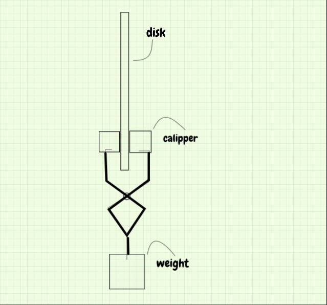
As for controlled caliper force, one could use a scissor mechanism with a hook on the bottom which could be loaded by the desired weights as per the schematic diagram.

For clarity, some parts are not shown.

balast brake

$\endgroup$
1
  • $\begingroup$ Thanks for this. This is definetely a true "mechanical" way to implement a constant clamping force. Simple yet efficient. I really admire it whenever I come across such an elegant solution. $\endgroup$
    – NMech
    Commented Oct 3, 2020 at 18:44
3
$\begingroup$

The basic thing you are looking at is a dynamometer - a generator mounted on trunnions to measure the reactive force.

So, look at those then use a smaller motor as a generator - the ones I used were capable of controlling 100 to 150 kW - a bit large for what you describe.

$\endgroup$
1
  • $\begingroup$ Yes 100 to 150 kW is almost two order of magnitde greater to what they were testing... However, it might be worth pursuing $\endgroup$
    – NMech
    Commented Oct 3, 2020 at 18:34

Your Answer

By clicking “Post Your Answer”, you agree to our terms of service and acknowledge you have read our privacy policy.

Not the answer you're looking for? Browse other questions tagged or ask your own question.