2
$\begingroup$

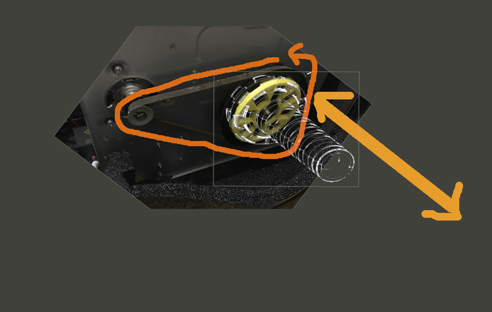
I have a motor that I have created a simple adapter for; this lets us attach any parts we might design to solve the final problem:

I would like to convert the motors motion to oscillating motion in two directions from one.

The motion I would like

The classic "woodcutter" solution to this is:

The woodcutter solution

However that does not give me the throw I would like for the final motion in either direction. Ideally this mechanism will sit on the floor - which SORELY limits the available "height" during rotation of any such "arm"

This motor has very high torque so it may be possible to move other structures while at a mechanical disadvantage in oblique (aka not smashing through the floor) planes?

In a nutshell after a couple of days thinking it idly over haven't managed a better solution yet.

Considered some sort of scissor motion? but couldn't firm up the details.

Is there a classic - obvious - solution to this problem?

Full disclosure: I have no formal training whatsoever in engineering.

Appreciate any assist.

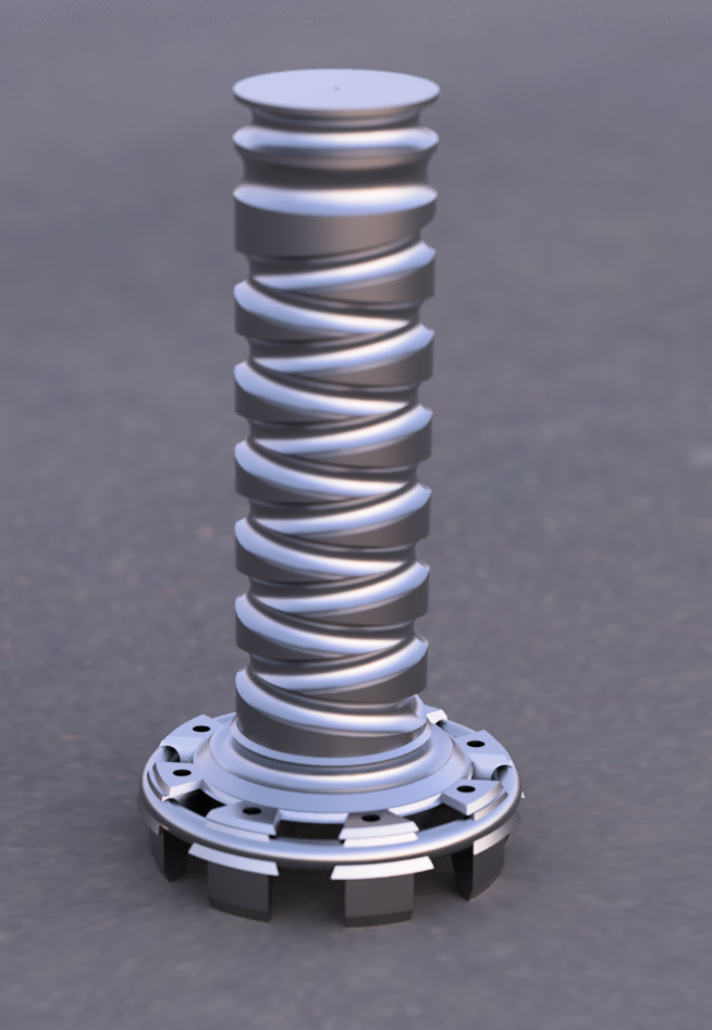
EDIT: I should add that I did think about some sort of reversing screw mechanism? but didn't manage to make that work yet in practice. perhaps That could be part of the solution but it doesn't solve the problem of throw either, well not without being really long and actually working. I might figure something out with this I guess?

Reversing Screw mockup, shown on adapter, just doodled up in fusion

This would result in motion in the other direction - which would be okay but if there is a more reliable or "better" way to get this motion would love to hear of it. Struggling with the screw solution.
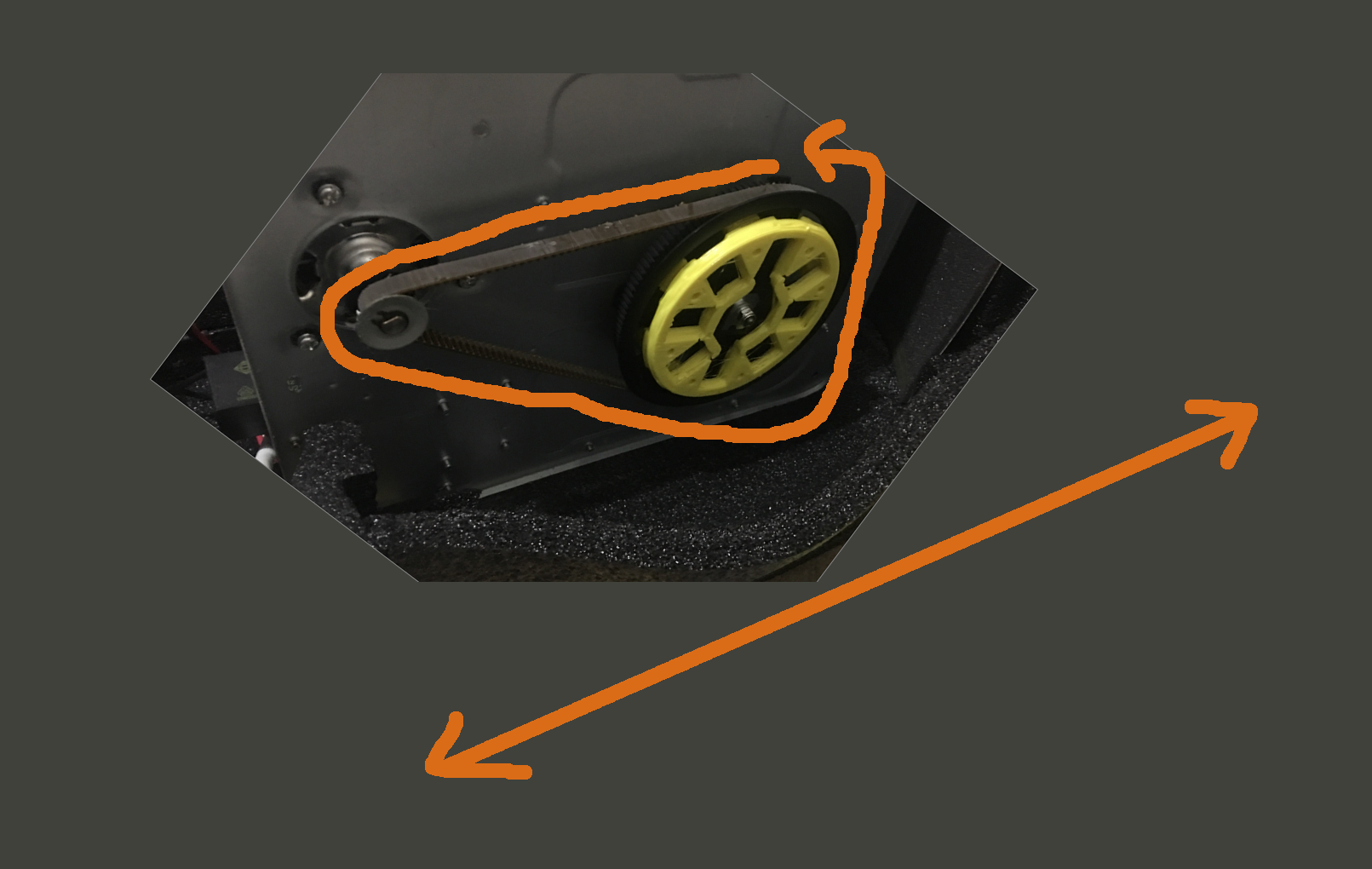
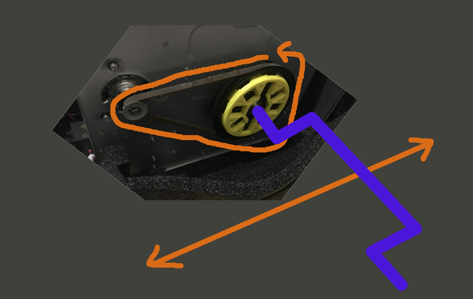
Other direction via a reversing screw

$\endgroup$
2
  • 1
    $\begingroup$ Use a cople of levers and control the pivot points. $\endgroup$
    – Solar Mike
    Commented Jun 7, 2020 at 6:34
  • $\begingroup$ thanks Mike. it's so obvious in retrospect. Ideally a smooth motion would have been the output but I will take what I can get. $\endgroup$
    – twobob
    Commented Jun 7, 2020 at 14:50

1 Answer 1

2
$\begingroup$

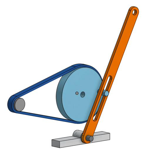
enter image description here

Figure 1. Something like this?

It will be faster as the drive pin moves through the lower section of the slot.

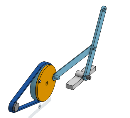
enter image description here

Figure 2. This option should result in more even speed on the forward and reverse strokes.

$\endgroup$
7
  • $\begingroup$ okay cool. Thanks. I shall probably accept this then. Did not mention that the motion should be ideally smooth so this would do it. Just gonna leave it a couple of days to invite other responses, just in case. Really appreciate the input. $\endgroup$
    – twobob
    Commented Jun 7, 2020 at 14:02
  • 2
    $\begingroup$ I always recommend that you wait a couple of Earth rotations to give the whole of humanity a chance to answer. You'll get much better insights than mine. (I'm electrical.) $\endgroup$
    – Transistor
    Commented Jun 7, 2020 at 14:30
  • $\begingroup$ fair play. I am a complete novice, this will probably do the job. I wonder if you would mind taking a look at my wiper problem? its a "let's guess how not to blow up this circuit" question, so... engineering.stackexchange.com/questions/36129/… just want to confirm the safest route to test it. $\endgroup$
    – twobob
    Commented Jun 7, 2020 at 14:38
  • 1
    $\begingroup$ I saw thatand can't imagine why there is so much electronics in the motor. I'd go for an old front wiper mechanism with a cable-drive which will give you the back and forth motion as well. $\endgroup$
    – Transistor
    Commented Jun 7, 2020 at 14:46
  • $\begingroup$ yeah right? I figured it was like an embedded 555, oh well. THANKS!! $\endgroup$
    – twobob
    Commented Jun 7, 2020 at 14:47

Your Answer

By clicking “Post Your Answer”, you agree to our terms of service and acknowledge you have read our privacy policy.

Not the answer you're looking for? Browse other questions tagged or ask your own question.