1
$\begingroup$

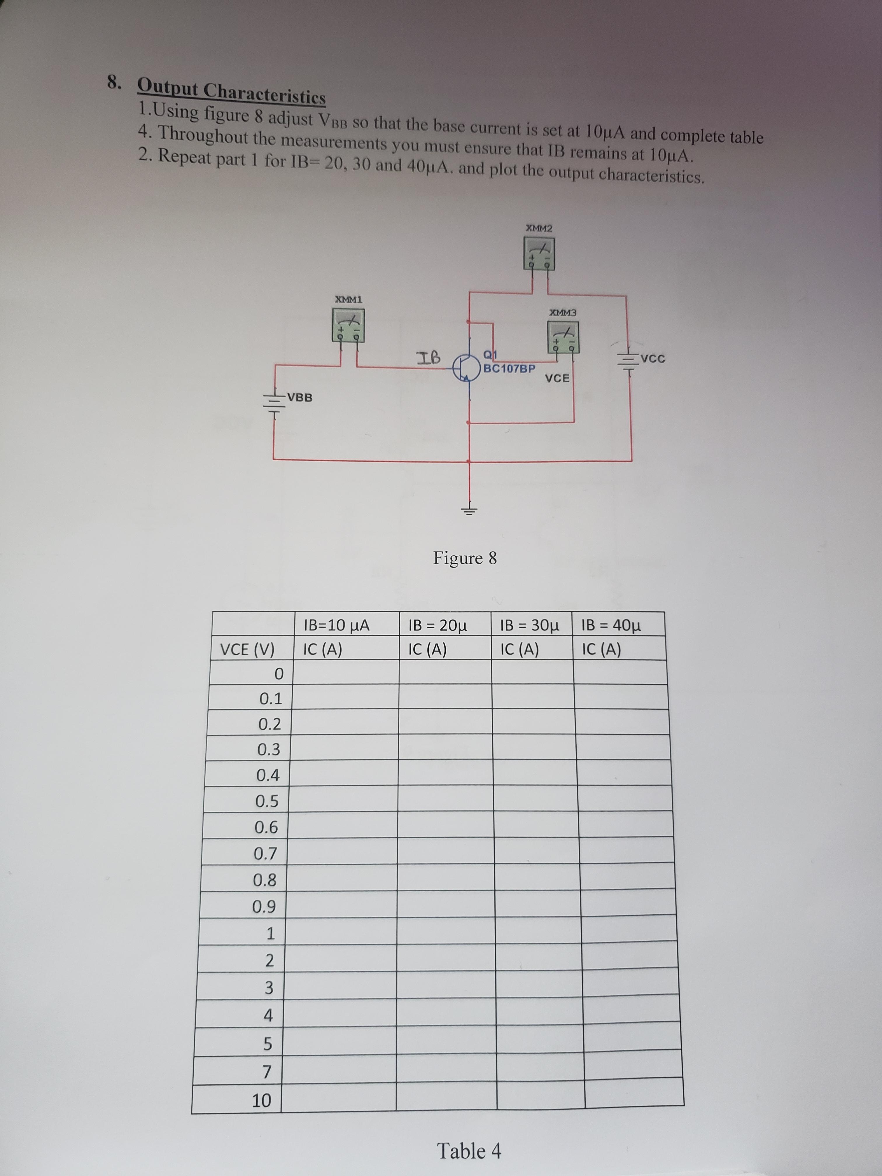
Ok, so I am pretty confused at the moment with a question that I have been given to work out by my lecturer and was wondering if I could get some guidance with it. I will attach images of the question and diagram of the circuit while trying to say how I believe it should be worked out. I have not yet had the classes for this question yet but wanted to get a better understanding of it before I go into the class.

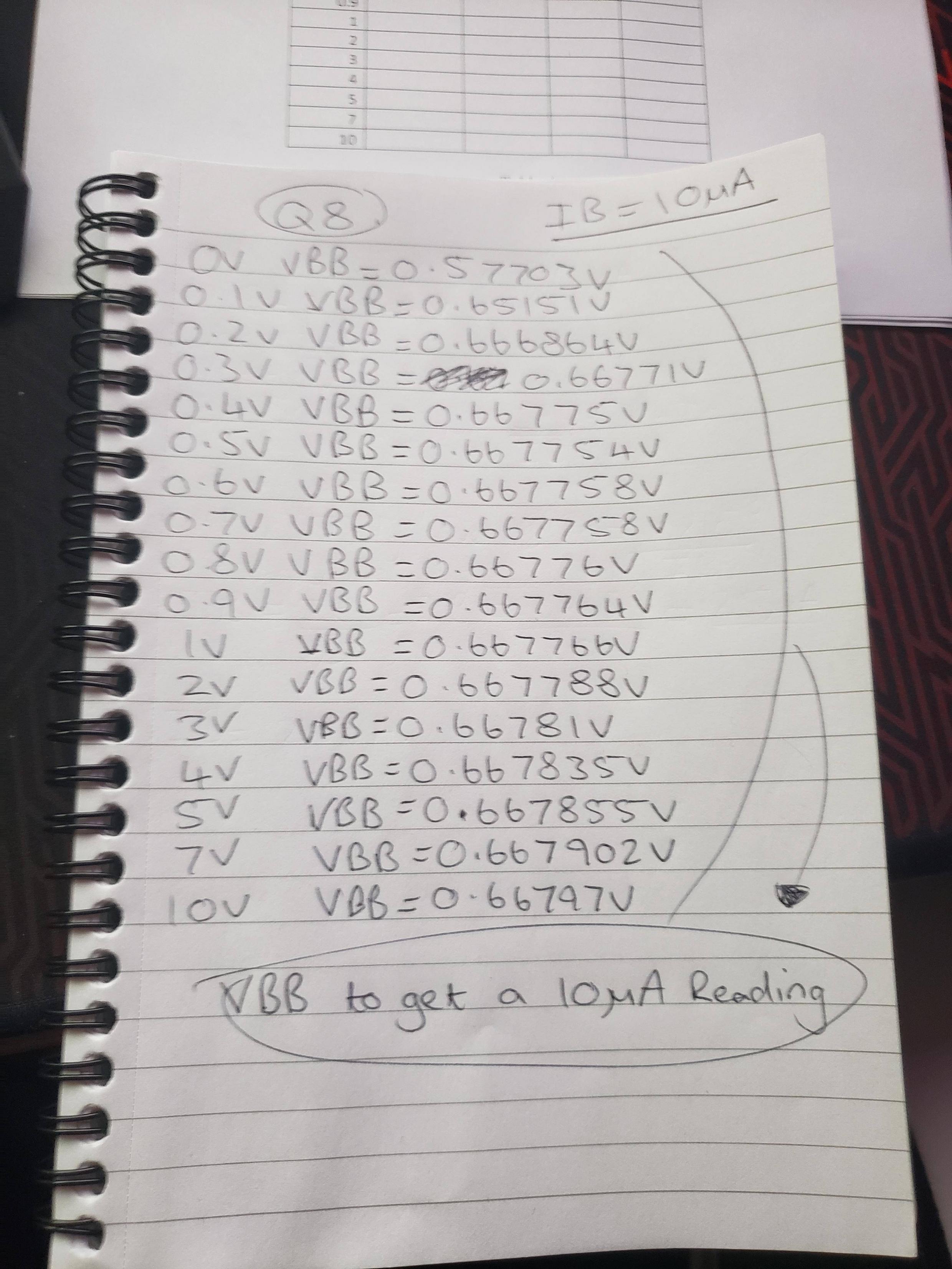
But I guess my main question would be this, is there a calculation that I could use to get a measurement of $I_b$ reliably without having to randomly guess numbers to get to 10 micro Amps and with regards to the results I have currently would you say I am on the right track? As I feel like I am complicating the question more than I should be.

So the question says "Using Figure 8 adjust VBB so that the base current is set at 10 micro Amps, and complete table 4."

Straight away I see that $I_b$ going to the base of the emitter has to be reading 10 micro Amps, I have a multi meter in place to make sure it is the reading I am getting but to do this I have to change the VBB voltage to make the multi meter read the right amount of Amps. So for me I have literally been spending 5 minutes trying to find out what 10 micro Amps is every time and id assume there is a much easier way to find this than spending 5 minutes doing 0.556677, 0.556679, 0.556683 etc until I find the right value.

I had also took note that I am given VCE which tells me if I change VCC to say 0.6V I will get the same reading on the VCE meter of 600mV and I have to work out $I_c$ which is the measurement on the multi meter from the transistor collector to VCC.

For some reason the attaching a imgur link wont work through the link section so I will leave the link below for the gallery of the 4 images.

Image 1

Image 1

Image 2

enter image description here

https://i.sstatic.net/o39yI.jpg

$\endgroup$
1
  • $\begingroup$ You adjust VBB to get IB to 10uA (XMM1 as an ammeter), then adjust VCC to get VCE (XMM3 as a voltmeter) and measure current IC (XMM2 as an ammeter). $\endgroup$ Commented Apr 19, 2020 at 3:55

2 Answers 2

0
$\begingroup$

Below is the equation for $I_c$

$I_c=\beta I_b$

$\beta$ is unique for the transistor. The value can be found in the transistor datasheet BC107B

In datasheet the parameter $\beta$ is usually labeled as $h_{FE}$

The $\beta$ value for BC107B from the datasheet is

enter image description here

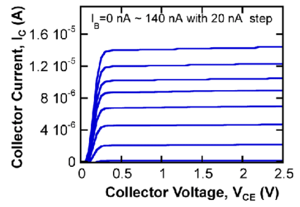
In short you are creating a graph similar to the image below for the BC107B transistor

enter image description here


References:

$\endgroup$
0
$\begingroup$

Wow, what an odd way to drive a BJT. The B-E junction is much like a diode in that no significant current flows through the base until ~0.6V but by ~0.8V the device is destroyed. Because the B-E juction voltage has a temperature coefficient, that 10uA at 25° might be 1mA at 26°. Base drives always have a way to have deterministic current, almost always by a resistor in series with the base or emitter. So ignoring the poor circuit design and assuming that one can adjust the voltage so accurately to have 10uA base current, Mahendra is right. Get the data sheet for the device, on the H-fe (or H-FE depending what you have) chart, find 10uA base current and cross to V-CE to get collector current. If no 10uA curve then interpolate. One last point, BJTs have wide specs. For example, if H-FE at Ic=10mA is typically 100, min might be 50 and max 150. You can't rely on typical H-FE values at all. You will run across these wide specs on FETs too.

$\endgroup$

Your Answer

By clicking “Post Your Answer”, you agree to our terms of service and acknowledge you have read our privacy policy.

Not the answer you're looking for? Browse other questions tagged or ask your own question.