1
$\begingroup$

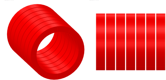
I have a series of copper coils with ¼” cooling plates between each coil. The cooling plates will be manufactured from aluminum and cooled using copper tubing. There are seven in series, and a plate in between each but theoretically this should be able to be expanded to any number of these plates in series. A picture is below of the setup. I went through a similar exercise with a different configuration which was very similar, but I am not sure if I got the final process correct.

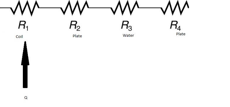
There is current flowing through all of the copper coils and the resistance and current are known. What I originally came up with was that the final temperature of the copper would be Tc=P*R_th +Tw where R_th is the total thermal resistance and Tw would be the temperature of the water. the thermal resistance would just be the addition of the thermal resistance due to the water (convection) as well as the resistance to travel the width of the insulated plate and the copper along the axis, but I am not sure how to go about this when all of them are in series and are simultaneously heating and cooling.

Getting the convection coefficient for the coil cooling is something that I am not worried about, I am just trying to get the equation that would describe this. I am looking for the final temperature of the coil (red) after everything has settled to it's final temperature. I don't know if this can be achieved in steady state or if a transient process must be taken. The coil schematic
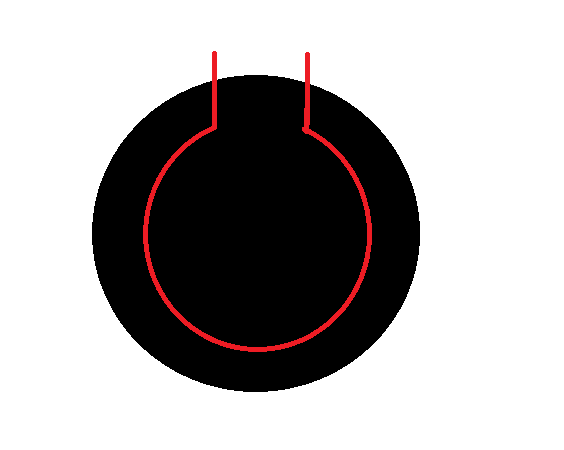
Here is the cross section of the cooling plate in between each wire coil. The plates are in the white spaces shown. The black represents the circular cooling plate. The red is the geometry of the cooling tube which sits in each plate and carries flowing water. Cooling Plate schematic The schematic of heat generation and thermal resistances is down below, but would be in series with almost 7 others of the same variety. Note that the pipe carrying the water does not cover the whole area so it may not be beneficial to look at the problem as all the heat traveling through the piping (hence the two plate resistances) or if there is some way to reconcile that.
Schematic

$\endgroup$
6
  • $\begingroup$ Yes, the white spaces are where the cooling plates are to be attached and there is uniform heat generation due to a current running through all of the red coils. The coils are exposed to air on the outside. I will attach a picture of the cross section of the cooling plate. The coils are copper, the cooling plates are aluminum, and inside of each of the cooling plates is a wire which runs in the shape of a circle made of copper. Inside this wire is the water which is used to cool the wires. $\endgroup$
    – alcopo63q
    Commented Jul 12, 2019 at 15:13
  • $\begingroup$ @JeffreyJWeimer We can probably assume that the flow inside this pipe is going to be turbulent to simplify any calculations for the convection coefficient is you touch upon that. I am not sure how to tackle the fact that the heat generation is happening at multiple points along the wire and that each point is spreading different distances and contributes different amounts to the total heat gain. $\endgroup$
    – alcopo63q
    Commented Jul 12, 2019 at 15:30
  • $\begingroup$ I will make a drawing when I can, but that is impossible at this moment. Even so, the drawing will not look any different from what I have drawn. The cooling plates are circular. They sit in between each coil. Inside the cooling plate is a tube that runs circularly through the plate and comes out in the crude drawing. That tube carries the water. That is the only place where water is actually flowing. The water does not flow inside the coils. It does not ever touch the coils. I guess ambient air temperature would be the only thing you could potentially say stays at a constant temperature. $\endgroup$
    – alcopo63q
    Commented Jul 13, 2019 at 12:26
  • $\begingroup$ Stagnant air sits on both the outside and inside of the coils. $\endgroup$
    – alcopo63q
    Commented Jul 14, 2019 at 13:02
  • $\begingroup$ Correction: there is no air inside the coils. The entire space in-between the red coils is taken up by the cooling plates. Stagnant air only resides on the outside of the coils. $\endgroup$
    – alcopo63q
    Commented Jul 14, 2019 at 13:40

1 Answer 1

0
$\begingroup$

Let’s assume that the tube is small in radius. Also assume the power input $P$ to the surrounding coils is constant with angular position. Finally, assume that the plates and coils are essentially isolated to heat flow; all power input to the coils leaves only through the water cooling.

With these assumptions, the temperature profile in the water coil can be taken to be a function only of angular position according to the equation below with $\theta$ in radians.

$$ \frac{T - T_i}{T_o - T_i} = \frac{\theta}{2\pi} $$

This is independent of how much heat is added along the coil. The output temperature of the water $T_o$ is found from an overall energy balance on a coil segment with water mass flow and specific heat capacity.

$$ \dot{m}\tilde{C}_p\left(T_o - T_i\right) = P $$

When the coils are perfect thermal conductors, the angular temperature profile in the water tube will be duplicated in the coils.

When you add convective heat flow out from the external wall of the coil, the final water temperature will be lower and the coils will have a radial temperature profile superimposed on the angular profile.

$\endgroup$
3
  • $\begingroup$ Well, I know that not all of the heat leaves through the cooling channels and the coil is constantly changing. The coolant is also constantly changing and so I don't think this would work in my case. In addition, there are 7 of these cooling channels and they are not all placed in the same spot. Therefore setting up a thermal resistance equation would have power entered at different spots. I do not think you can just lump everything into it simply this way. At least, I do not think that simplification of the problem would give me an accurate answer. $\endgroup$
    – alcopo63q
    Commented Jul 16, 2019 at 17:20
  • $\begingroup$ I would eventually like to be able to tell the temperature of the water in each channel as I believe these may differ across the channels and the temperature of the coil itself. This may have to be done by breaking it up into several small segments and also may reveal a gradient or at least segmented average temperatures across the seven pieces. $\endgroup$
    – alcopo63q
    Commented Jul 16, 2019 at 17:21
  • $\begingroup$ The answer that I have given shows the foundations for the heat transfer principles that should be applied. A model that uses series resistors is overly simplified if not wrong for what is becoming a multi-component, two/three dimensional system. I cannot address these additional complications adequately here. Perhaps this is the point where you have to hire a professional to do the analytical analysis and/or the numerical modeling. $\endgroup$ Commented Jul 17, 2019 at 13:06

Your Answer

By clicking “Post Your Answer”, you agree to our terms of service and acknowledge you have read our privacy policy.

Not the answer you're looking for? Browse other questions tagged or ask your own question.