0
$\begingroup$

There is this problem I can't figure out. One measurements wheel needs to be attached to a slowly moving but wildly shaking and twitching construction machinery. I am trying to greatly absorb the shocks by means of a spring pictured below (and a damper not pictured). The wheel also needs to move in parallel with the machinery.

In this design I have coupled the wheel to the machinery by a guided spring. The spring stretches and compresses between two metal plates with the upper plate sliding over rod1 and rod2. I am not a mechanical engineer, but I think there will be problems due to the way the wheel is dragged alongside the machinery, i.e. there will be some friction between the two rods and the upper metal plate, causing the spring guide not to work very well.

If this is the case, what is a standardized known to work manner to approach this problem - shock reduction / isolation between the machinery and such a wheel ?

enter image description here

$\endgroup$
2
  • 1
    $\begingroup$ torsion arm trailer suspension - northerntool.com/shop/tools/… $\endgroup$
    – Phil Sweet
    Commented May 6, 2019 at 1:35
  • $\begingroup$ @PhilSweet Very interesting; I'll try to keep the costs low for now. $\endgroup$
    – kellogs
    Commented May 6, 2019 at 7:15

2 Answers 2

2
$\begingroup$

If all three things labeled "joint" in your drawing are hinges, I don't think the spring will do anything at all.

You don't say what you are trying to measure here, but the design doesn't seem to support the wheel properly. For example what happens it the wheel "gets stuck" in a depression? It looks like the linkages will just twist, and leave the wheel "stuck" while the machine moves forwards. Whether the wheel unsticks itself, of something gets permanently bent or breaks, seems a matter of luck rather than good design.

I think the first thing you need is a linkage that constrains the axle of the wheel properly so it can only move up and down, and not twist in any direction. In two dimensions a four-bar linkage would do that, but you also need something so the wheel can't move forwards or backwards out of step with the machine it is attached to.

Think about adding a damping mechanism after you have got that sorted out - though you might not need any damping unless the measuring wheel is very light.

$\endgroup$
1
  • $\begingroup$ Yes, they are just hinges. It won't ? Hmm, maybe I'll try it without that spring ... Also not figured there is a counterweight on the other side of the wheel. $\endgroup$
    – kellogs
    Commented May 6, 2019 at 7:25
1
$\begingroup$

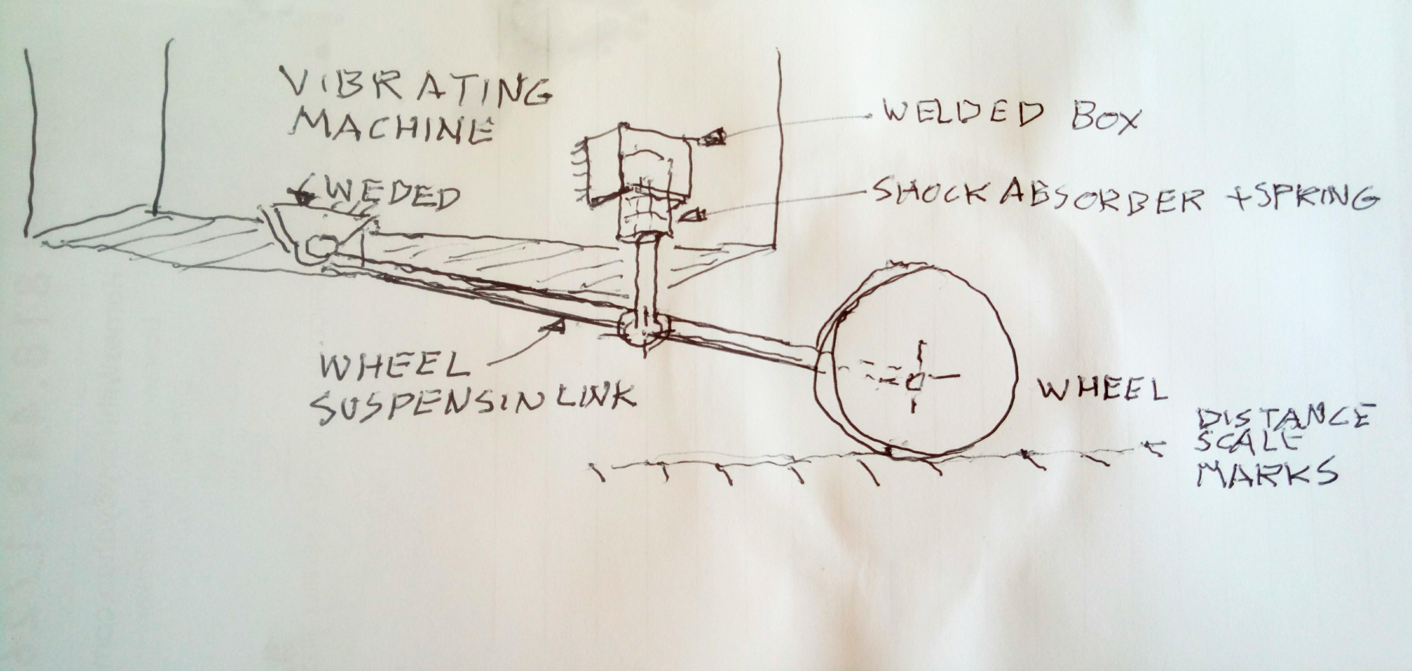
Here is a simple design as a starting point for you to modify according to what are your constraints and what are the data that you need to collect.

On the track of the wheel, there is a graduated scale that could be fit with acceleration sensors or what not.

diagram

$\endgroup$
1
  • $\begingroup$ That looks neat! Not sure how good of a job it would make at isolating the measuring wheel from vibrations and such. Ideally I want it perfectly isolated. $\endgroup$
    – kellogs
    Commented May 6, 2019 at 13:18

Your Answer

By clicking “Post Your Answer”, you agree to our terms of service and acknowledge you have read our privacy policy.

Not the answer you're looking for? Browse other questions tagged or ask your own question.