0
$\begingroup$

I apologize for the vague title. I know my problem, but I am having problems describing it in concise words, which is making it difficult for me to google.

I am building a CNC machine that is similar to a pick and place machine. I used extruded aluminum for the rails, and I am certain that everything is squared up. I had a local machine shop create a plate that has a grid of holes, so that I can attach "parts" that can be used by the CNC machine. However, this grid of holes is not machined at the tolerance that I need (budget constraints). I need a system for making sure that the "parts" are square to the cnc frame. One of my ideas was to use leveling springs similar to how you adjust a the bed on a 3D printer to be square with the frame. However, I am unsure if this is the best idea, and I would like a second opinion.

It is important that the machine has a resolution of 200um (if you were to move in a straight line across the machine ~500mm all parts that should be on that line should not be more than 200um above or below it). I know that some solutions maybe more expensive than having the plate machined to lower tolerance, but if I were to mass produce this machine I would like a way to adjust the alignment of parts.

Thank you for taking the time to read and/or answer my question!
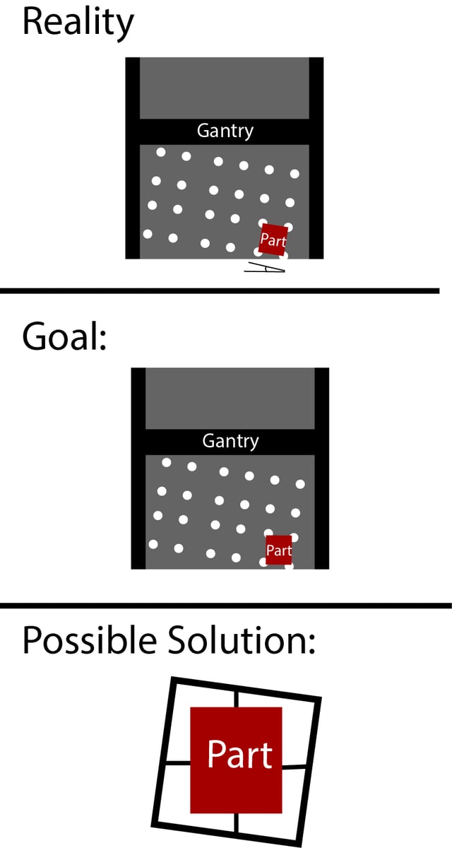
enter image description here

$\endgroup$
4
  • $\begingroup$ Are the hole locations within the required tolerance of each other but the whole grid rotated too much relative to the plate, like in the diagrams, or are they at irregular positions? Also, I don't understand your Possible Solution diagram. Can you explain that? $\endgroup$ Commented Jan 21, 2019 at 18:35
  • $\begingroup$ The hole positions are irregular. Thank you for asking for clarification. The possible solution is to use use leveling springs (the black lines). I should have left out the "possible" solution. It is confusing and may not work. $\endgroup$
    – David F.
    Commented Jan 21, 2019 at 18:41
  • 1
    $\begingroup$ What's wrong with bolting them on with some clearance in the bolt holes so you can locate them with a dial indicator or engineer's square while tightening the bolts? Or fix dowel pins to the parts which are positioned to compensate for the error in hole positions? $\endgroup$ Commented Jan 22, 2019 at 12:56
  • $\begingroup$ Can you clarify... Are we looking at a top view of your machine? Is this a gantry styled, CNC router type arrangement? You mention "square", In what directions? From what your talking about with leveling screws, are you talking about flatness with respect to your XY plane? Or using the screws for moving the part around in the XY plane?If your talking about alignment in your X direction as it looks in the 2nd pic, indicating the feature you want aligned to the x direction with a suitable dial/test indicator is the best way. Not the fastest way. $\endgroup$
    – Corey
    Commented Mar 7, 2019 at 17:15

1 Answer 1

0
$\begingroup$

At a bare minimum,I would accurately mount a "fence" in one of the directions, X or Y. pretty much a piece of tool steel stock, or anything precision ground say, 1/4" x 1" wide x however long you can fit, mounted to the working table at one of its ends. The fence should be indicated to within .001" or so, alignment with whatever axis you pick. Now when you go to put parts on the work table, you can use squares and parallels, referenced off your fence which you know is whiten .001" alignment of a particular axis(square to the other), to accurately align whatever feature on the part your using as the parts reference. Then your parts will be accurately located withe respect to the fence, which is accurately located with respect to the axis' of travel. This would be the most "universal" way to set up your machine. If your working on the same parts constantly, I would design fixtures for holding them. All depends how fast you want to work. Dowel pin the fence to the table so it can be removed and put back without indicating again.

$\endgroup$
1
  • $\begingroup$ Corey thank you for your reply! I apologize for accepting your answer so late. This was the route that I went. $\endgroup$
    – David F.
    Commented Apr 23, 2019 at 16:37

Your Answer

By clicking “Post Your Answer”, you agree to our terms of service and acknowledge you have read our privacy policy.

Not the answer you're looking for? Browse other questions tagged or ask your own question.