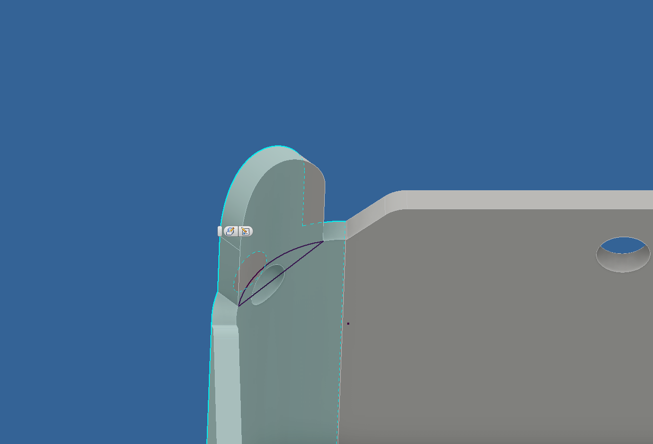
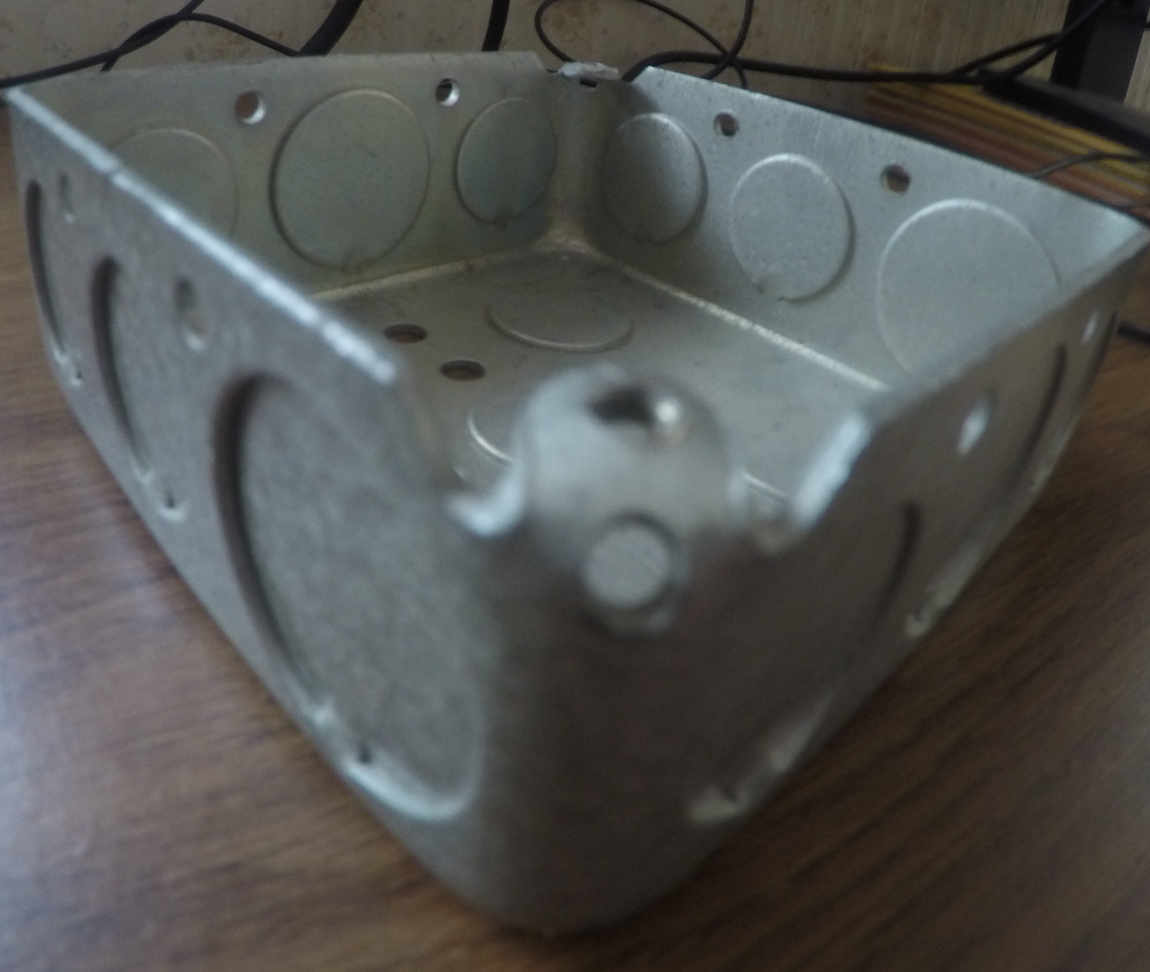
I am trying to bend this sheet metal concave lip inside the electrical box. I also need the top of the bent part below the top edge of the outside of the box.

$\begingroup$
$\endgroup$
7
-
$\begingroup$ How is this being manufactured? Which vend happens first? Are you relying on material stretch or are you adding notches etc to relieve? I can help with modelling but your priority should be design for easy manufacturing and putting a fold there should be avoided if possible. What are the design constraints that mean you need this as shown? $\endgroup$– Jonathan R SwiftCommented Oct 19, 2018 at 15:44
-
$\begingroup$ "someone just wanted this in Inventor form" - so there's a drawing to reference? Presumably the tab should be flat after the bend? Always question! I'll be able to get to my laptop this evening and will model this for you then - can think of a few ways that ought to work, but want to test them first! $\endgroup$– Jonathan R SwiftCommented Oct 20, 2018 at 7:36
-
$\begingroup$ Much obliged, Sir. We are given the part, and we reverse engineer it into inventor, using a protractor, and other forms of measurement tools. We put the measurement down to the hundredths. And whatever part the boss likes and the client likes the best, is the one that gets approved. $\endgroup$– JaredWolfCommented Oct 20, 2018 at 13:34
-
$\begingroup$ So any chance of seeing a photo of the original object? $\endgroup$– Jonathan R SwiftCommented Oct 20, 2018 at 16:22
-
$\begingroup$ Oh my god, OK. Right. And do they need this to be modelled 100% using sheet metal tools, i.e. so it can be 'unfolded', or is this so it can be used in computer renderings etc? This will require surface modelling, or at the very least lofts, etc. The issue is, there's no 'fold line' it's just relying on the way the metal deforms naturally to deal with the corner... $\endgroup$– Jonathan R SwiftCommented Oct 20, 2018 at 17:51
|
Show 2 more comments
1 Answer
$\begingroup$
$\endgroup$
2
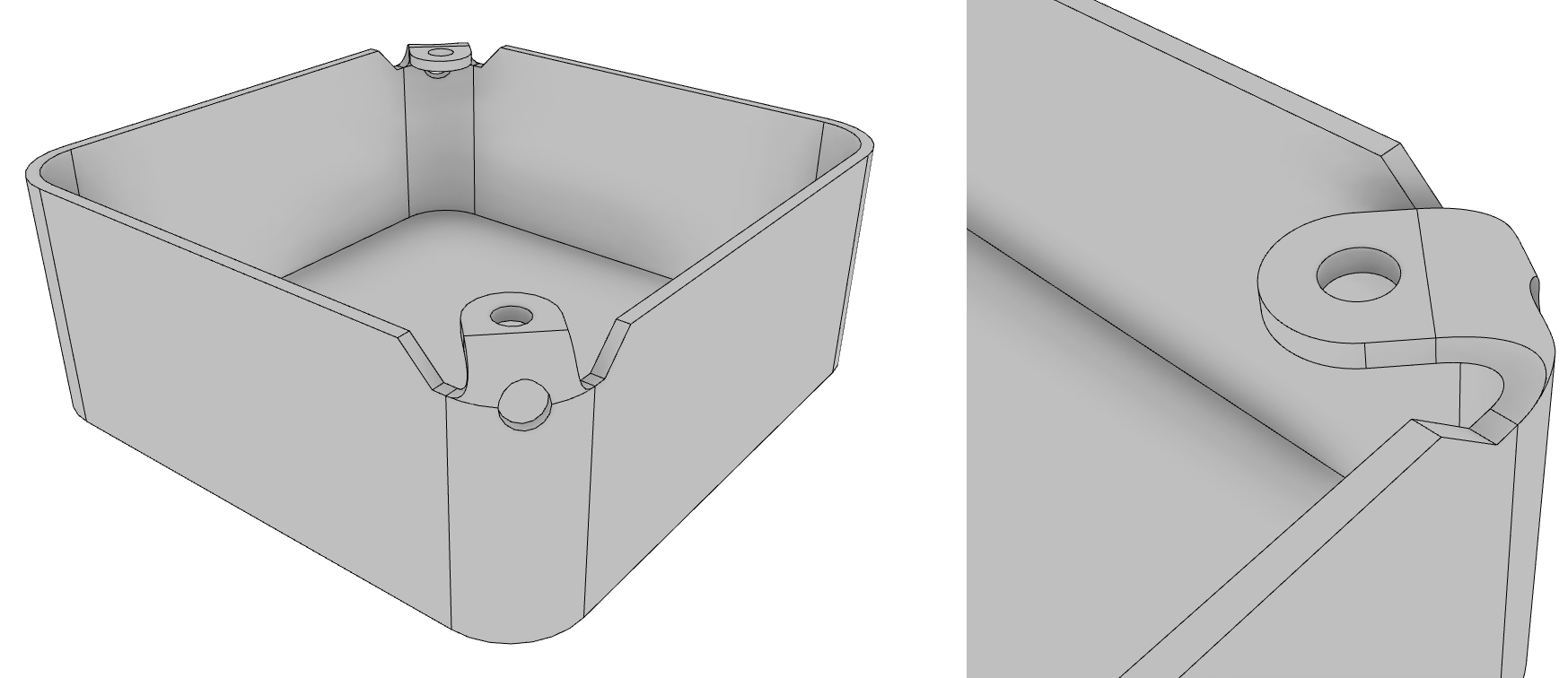
I've had a quick go - it's hard to be more precise without measurements, and it should be stressed that the actual bent shape of the metal is very weird, and difficult to model. Hopefully this will give you a method to get started with, however, and you can adjust spline handle lengths and dimensions etc. as you go.
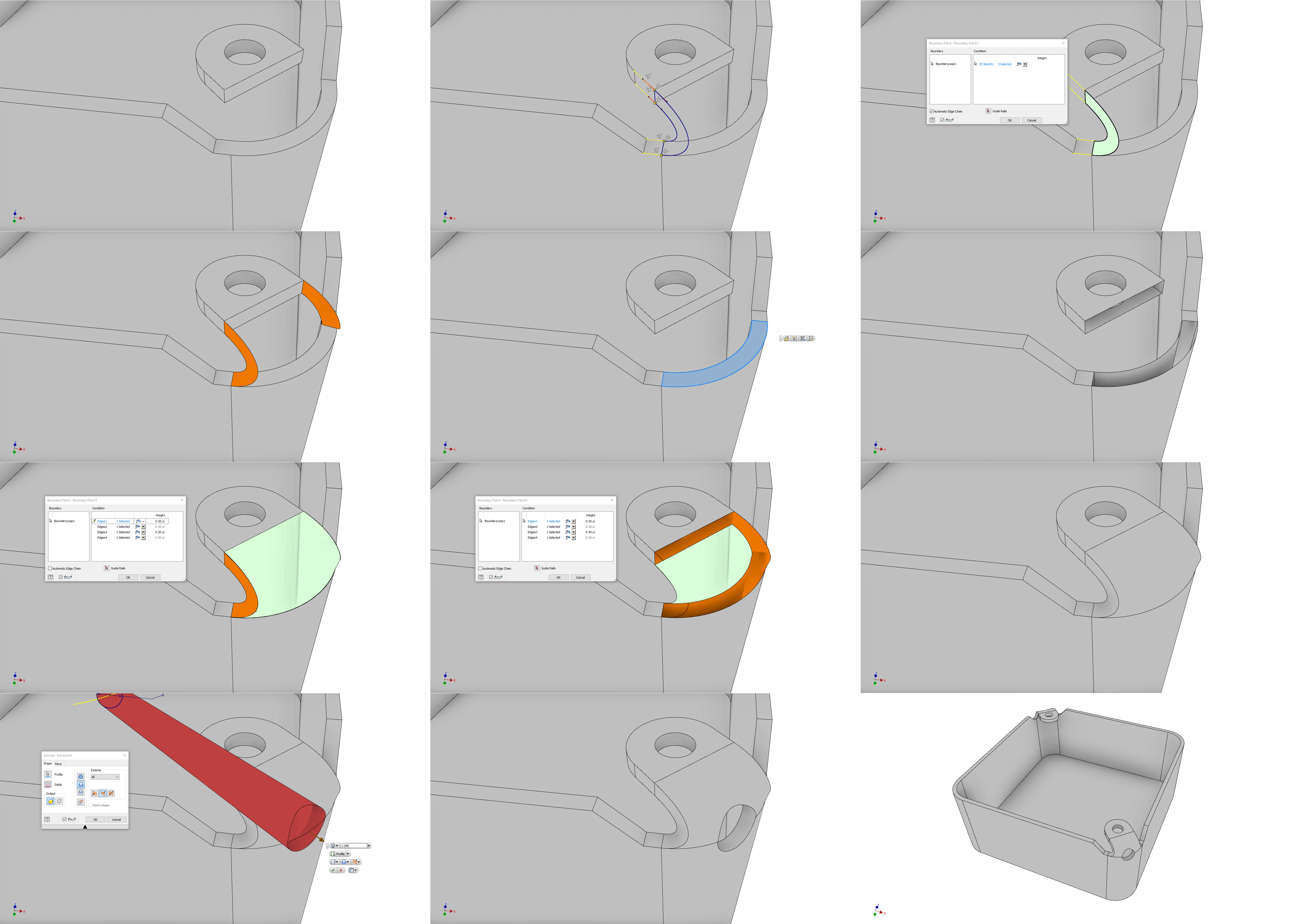
The steps go as follows:
- Model the 'non-weird' bits, and float them in space.
- Create a 3D sketch with splines connecting the two bodies, set to be tangent to the edges. Right click the spline, and click "activate handle" to give yourself more control over its form. Also include lines connecting these splines to create a closed loop.
- Use "Boundary Patch" to generate a surface body inside the 3D sketch you just created
- Mirror the Surface Body to create a symmetrical copy of it.
- Sketch on the surface that will have the bend attached, and draw two lines. Use the split tool to split the surface accordingly.
- Use the Delete Face tool to remove the faces of the solid body which will join the bent part. It has now also become a surface body.
- Use Boundary patch again to create the outer face of the bend this time with automatic edge chain deselected, and selecting the edges of the surface bodies, rather than anything in a sketch. Set a Tangent Condition on the edges that are 'bent', and leave it as Contact for the 'cut' edges. of the tab.
- Repeat for the inner face of the bend
- Use the 'Stitch Surface' Tool, and uncheck "Maintain as Surface" to merge all the surface bodies and create a solid.
- Create a new work plane at a slight angle, and sketch a circle on this for use as an extrude cut for the cutout hole. This is an approximation, of course. You could use the draft tools to create a taper in this hole closer to real life, but without the object for reference, I've decided this is good enough - you can experiment with other methods!
- All Done
- Mirror/Rotate/Whichever to create the opposite side of the box. Also, to create a 12th point on this list and make my image nicer :) High resolution version available here
-
$\begingroup$ I used a flat tab in step 1), because, despite seeing that it was from a casting that probably had a rounded tab before being bent, I still had in my head that it was a sheet metal tab that would have been flat when cut. There's no reason this method wouldn't work if the floating tab in step 1) were to be convex, but I'm not going to update all the screenshots because I don't have time! $\endgroup$ Commented Oct 20, 2018 at 21:25
-
$\begingroup$ Which version of Inventor are you using? There's no way to private message on Stack Exchange, but if you have a Thingiverse account, drop me a message here: thingiverse.com/messages/compose?username=jonathanrswift and I'll arrange a link/time where I can go through modelling this via screenshare? The surface modelling tools in Inventor are clunky and certainly limited, but they can save you, so it's worth having a quick primer on how to make them work! 3D Sketches, particularly, are a very powerful tool... $\endgroup$ Commented Oct 26, 2018 at 6:37


