1
$\begingroup$

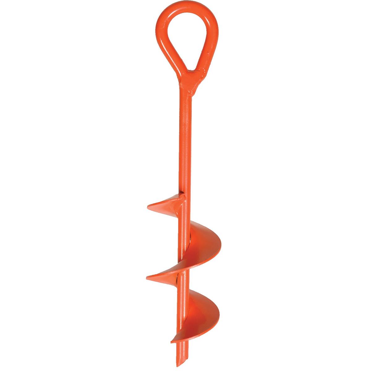
I'm a high school student who hasn't had the pleasure of taking physics yet, so forgive me if the answer is obvious. The problem I have involves an earth anchor drilled vertically into the earth.

https://static.gemplers.com/img/auger-style-earth-227706-lrg.jpg

I am trying to figure out the equation that would give the highest amount of permissible force uniformly distributed on the exposed top part before the anchor would rotate. Just a force perpendicular to the vertical auger. What I mean by rotate is that it would pivot at a point halfway down the auger, like a lever with a fulcrum in the middle (x axis), and not unscrew itself from the earth (z axis). Of course this would be easy if it were in air, but I'm lost at how to calculate it in dirt. I came here from Physics Stack Exchange. The auger would be 9 inches long and immersed in 1.52 g/cm consistently dry soil. Any help would be greatly appreciated.
$\endgroup$
4
  • 1
    $\begingroup$ this is not a trivial problem. read up on granular resistive force theory. $\endgroup$ Commented Aug 21, 2018 at 13:06
  • $\begingroup$ If you're going to reference axes, please draw those axes. Are you asking how much force is essentially required to pull this up, like a tent stake? When you rotate, you rotate about an axis, not along an axis. Can you quantify the "dirt" the auger is in? Is it sand, or a sandy loam, or swampy mud, clay, topsoil, etc.? Is it loose or compacted? How wet is it? As @MohammadAthar stated, this isn't a trivial problem. $\endgroup$
    – Chuck
    Commented Aug 21, 2018 at 13:41
  • $\begingroup$ @Chuck I know that it takes 440 N to pull the particular stake out of the ground. The dirt the auger is in is sandy topsoil, constantly dry, 0-moisture dirt with a density of 1.52 g/cm^3. $\endgroup$ Commented Aug 21, 2018 at 17:25
  • $\begingroup$ It is good to know that the default directions of axes is not set in stone. It is especially common to see y up drawings in mechanical engineering and physics $\endgroup$
    – joojaa
    Commented Aug 23, 2018 at 4:20

2 Answers 2

0
$\begingroup$

At your level this is a major question so to keep it simple, you are asking about moments aka turning force.

The issues you face are calculating the specific friction coefficient of the particular rock into which you are embedding the tool. That can only be done by soil analysis by a geotechnical lab.

In this specific case you can make it quite simple to calculate by pushing a sharp rod into the ground with a device to measure the force needed to push it 100mm into the ground. That would tell you the minimum amount of force required to turn the auger.

The equation is $F=\frac M{A}$

This means that the force required to penetrate the soil is going to increase proportionately to depth and add it does it will require greater force due to increasing mass of soil being sheared. Since the acceleration is actually constant velocity, this is the expected result.

Ideally you would put a strong pole through the auger eye and turn the auger with that pole. The longer the pole, the less applied effort required to force the auger deeper since we calculate moments of force perpendicular to the line of action which generates torque.

$F*d=R_f$ where $R_f$ is the resultant force. F is applied force and "d" is the perpendicular distance to the radial centre of the fulcrum. In this case that fulcrum point is the auger itself.

Hope this clears it up a bit.

$\endgroup$
0
$\begingroup$

I am going about explains this question at the level of high school physics.

Let's assume you auger blade covers 2 full circles at length of embedment of 1.5 feet. And assuming the radius of blades 6 inches the diameter of the bore as 1 foot.

So the surface of the earth resisting torsion is either $1.5\pi\times1 = 1.5\pi$ feet or a expanded length of $2\times2\pi\times1.41 = 5.64\pi$ times shear strength of your soil, typically at approximately 100 lbs/ft2.

So picking the bigger shear as the one on the surface of the blade versus the bore, we get $564\times 0.5= 282\text{ lbs ft}$ torque. This is dislodging of the soil's resistance which is not large enough to create a hinge in the shaft.

Now we look at the other end and try to see how much force the shaft can take before it yields and creates a plastic hinge.

Let's say the diameter of the shaft is 1 inch and it's made of steel with 25 p.s.i. torsion strength.

Torsion strength of a shaft is

$$z\tau= \dfrac{\pi}{16}d^3\times25000 = \dfrac{\pi}{16} \times 25000 \approx 5000\text{ lb in}$$

So you need to apply 5000 $lb.in^1$ total torque to the top part before it starts to develop a plastic hinge regardless of the soil it is boring.

Edit

After new comment by OP, here I attach my previous answer to a similar question.

$\endgroup$
1
  • $\begingroup$ the goal is not to rotate about the screwing/unscrewing axis, but one that is normal to that. $\endgroup$ Commented Aug 22, 2018 at 19:44

Your Answer

By clicking “Post Your Answer”, you agree to our terms of service and acknowledge you have read our privacy policy.

Not the answer you're looking for? Browse other questions tagged or ask your own question.