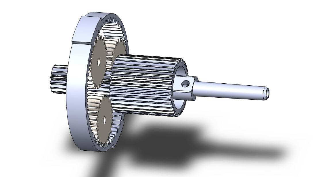
I am very new to gears I am fairly confused about planetary gears. I want to know the load on the gears contact point between the sun and the planets and the planets and the ring, assuming the ring not moving. Given I have the solid works file ,the pressure angle, and the gear ratios, I can easily calculate the distances, teeth numbers, etc. I also know the initial driving torque of the sun gear. So, my question is, utilizing the solid works file and the driving sun gear torque how do I calculate the load on the contact point for each of the gears? Is there a general equation I can use without knowing the power and the rpm?
1 Answer
Calculating forces on teeth
While determining the forces acting on the teeth of each of the gears requires using Newton's 2nd Law, the calculation of these forces is surprisingly involved. This is because it is important to find the locations on the teeth where these forces act, and the directions of the forces: it is important to analyse the geometry of gears.
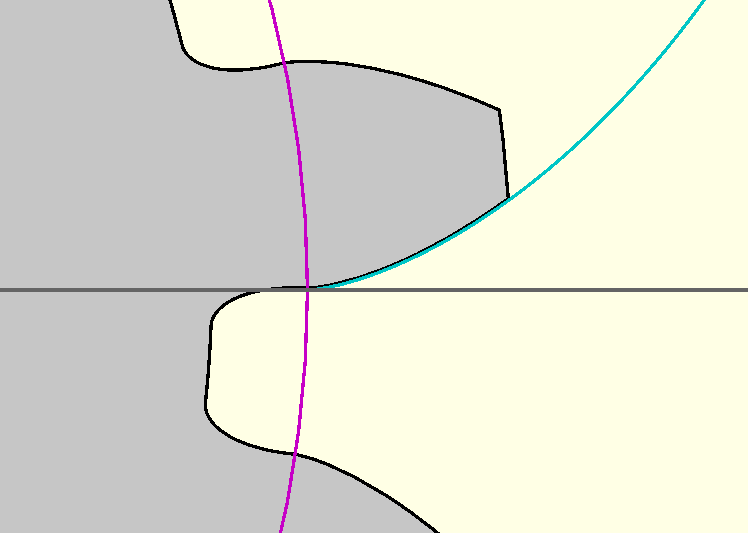
Almost always in industry will gears be involute (with the notable exception of gears in clockmaking), and this indeed appears to be the case of the gears in your images. Involute gears have teeth whose shape are based on the involute curve, as shown in Fig. 1:
Fig. 1: Close-up of a typical involute gear's tooth.
The involute curve is displayed in cyan, and defines the shape of the part of the tooth that is designed to make contact with the teeth of the mating gear. It is this involute profile that is responsible for the smooth transmission of power from one gear to the next, and is the location of the force that one gear tooth exerts on another. For gears with sufficiently many teeth, the involute profile of the tooth starts at the base circle of the gear, shown in magenta in Fig. 1, and extends to the tips of the teeth. The involute curve can be expressed as a parametric equation with parameter $t\ge0$:
$$ \begin{matrix} x(t)=r_b(\cos{t}+t\sin{t}) \\ y(t)=r_b(\sin{t}-t\cos{t}), \\ \end{matrix} \tag{1} $$
where $r_b$ is the base circle radius.
Note $r_b=r_p\cos{\phi}=0.5Nm\cos{\phi}$, where $r_p$ is the pitch circle radius, $N$ is the number of teeth on the gear, $m$ is the module and $\phi$ is the pressure angle.
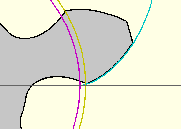
Aside on undercutting: For standard gears with less than 18 teeth, the involute profile might not reach down to the base circle, significantly so as the number of teeth becomes very small. This undercutting of the involute profile is often a bi-product for some of the manufacturing methods, and is generally undesirable. However, it can also be a necessary evil: for gears with low tooth counts, the lowest part of the involute profile obstructs the path of the tips of the teeth of the mating gear; undercutting provides the clearance necessary for the mating teeth to move without jamming. Fig. 2 shows the effects of undercutting on the involute profile for a gear with only 6 teeth:
Fig. 2: Close-up of a heavily undercut gear tooth.
While the mathematical involute curve (in cyan) does reach down to base circle (in magenta), the corresponding involute profile on the gear tooth itself does not: some of the involute profile has been lost to undercutting. This results in a reduction of the useful geometry of the gear responsible for smooth power transmission. Instead, the involute profile reaches down to a circle called the undercut diameter (in yellow).
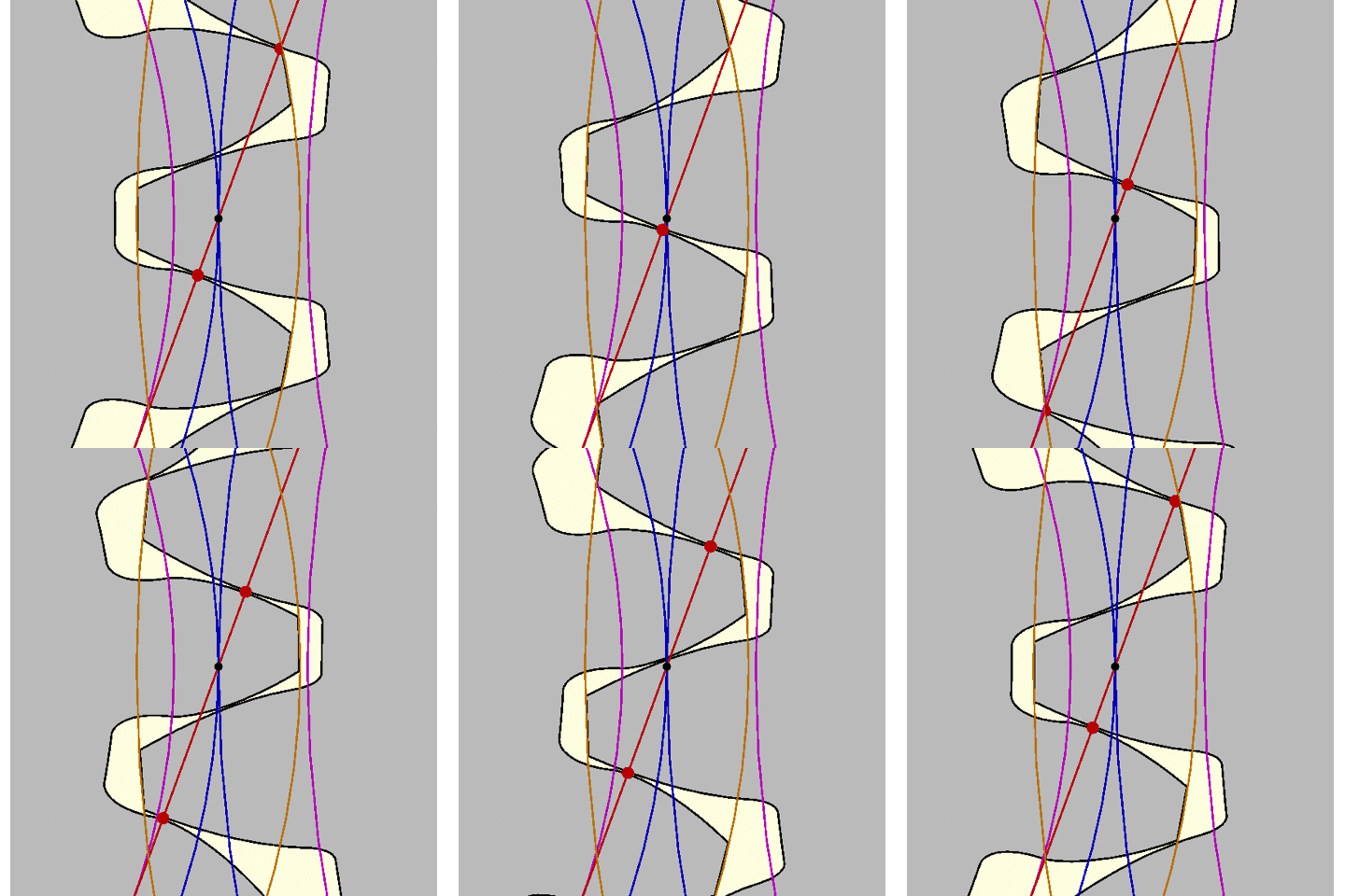
Pressure Line: The involute profile is important when considering the forces as a special feature arises from the contact of involute profiles of two teeth: as the gears rotate, the point at which teeth contact one another moves in a straight line called the pressure line, as shown in Fig. 3:
Fig. 3: Animation demonstrating how contact points move along the pressure line.
In Fig. 3, the base circles of the gears are shown in magenta. The pressure line is shown in red, with the points of contact as red dots. Note how the pressure line lies tangent to both base circles, and that the contact points move at a constant speed along this line. The blue circles are the pitch circles of the gears, and the orange circles are the outer diameters.
The angle the pressure line makes to the vertical is equal to the pressure angle. In the case shown in Fig. 3, the left gear is the driving gear, the right is the driven gear, and so the pressure line lie clockwise to the vertical. If the right gear was made the driving gear, the pressure line would instead lie anticlockwise. Note how the pressure line lies though the pitch point, i.e. the point at which the two pitch circles touch.
Most importantly, note how the involute profiles of the teeth at the contact point is normal to the pressure line. Therefore, the force that one tooth exerts on another will lie along this pressure line (hence its name!). Since the tooth forces run in a straight line, the distance between the line of action of the forces and the centre of one gear remains constant, this distance being equal to the base circle radius $r_b$. As a result of this, provided the input torque $T_i$ remains constant, the sum of the tooth forces will be equal to a constant value. For a pair of mating gears will negligible friction, this value should equal $F=T_i/r_b$.
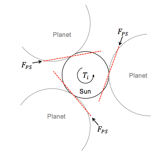
With this information, it is now possible to calculate the sum of the tooth forces one gear exerts on another: between the sun and planet gears and between the planet and ring gears. First, let's look at the sun-planet tooth forces. Let $T_i$ be the known input torque applied to the sun gear, and $F_{PS}$ be the unknown sum of the tooth forces that one planet gear exerts on the sun gear. Consider the forces acting on the sun gear, as shown in Fig. 4:
Fig. 4: Schematic showing the forces acting on the sun gear.
In Fig. 4, the pitch circles of the sun and planet gears are shown, with the pressure lines included in red, noting that the pressure lines should go through the points the pitch circles meet, rotated by the pressure angle away from the common tangent of the pitch circles. Note how the sum of the tooth forces act along these lines (the exact location along the pressure line at which these forces act is not important). To determine the sum of the tooth forces, applying Newton's 2nd Law would appear to be a sensible course of action. However, it is often satisfactory to just simply enforce static equilibrium of moments, ignoring dynamic effects, especially if the gears are travelling at relatively low speeds where the inertia forces are much lower than the tooth forces. In this answer, only static equilibrium will be considered.
When considering equilibrium, note how the fact that there are three planets engaging with the sun gear means that the total tooth force that each planet gear exerts on the sun gear (and vice versa) has effectively been split in three. The total sun-planet tooth forces for a three-planet planetary gear set turn out to be as follows:
$$F_{PS} = \frac{T_i}{3\times 0.5N_S m \cos{\phi}}\tag{2}$$
where $N_S$ is the number of teeth on the sun gear. Note how the value of the module $m$ should be the same for all the gear in the planetary gear set.
The static equilibrium of moments can be considered for one of the planet gears, and upon doing so, it can be seen that the sum of the tooth forces the ring gear exerts on one planet gear is equal to the sum of the sun-planet tooth forces.
We are therefore able to determine the sun-planet and planet-ring sum tooth forces. Note though that this is the sum: between any two mating gears, it is possible to have more than one point of contact at any one time, as can be seen in Fig. 3. If there are multiple points of contact, it can be assumed that the sum tooth force is split equally between the two contact points. The more contact points, the less load individual teeth will experience. (Note however that some gears may have considerable profile inaccuracies from its manufacturing, to the extent that, even if in theory there may be multiple points of contact, all the force falls onto just one contact point.)
To determine the force applied onto a single tooth, it is necessary to determine the number of contact points. Note that for a given pair of meshing gears, this number will fluctuate between two values over times; in Fig. 3, in can be seen that the number of simultaneous contact points varies regularly between 1 and 2. To determine this number, the contact ratio is calculated: this is defined as the length of line of action divided by the base pitch. The line of action is the portion of the pressure line along which contact points exist, and the base pitch is the distance between two neighbouring teeth measured along the base circle, equal to $p_b=\pi m \cos{\phi}$. The contact ratio can be interpreted as the average number of contact points, and so can be rounded down and up to obtain the two integer values of number of contact points. Often the line of action is bounded by the outer diameters of the two gears, and so the contact ratio can be calculated as follows (equation adapted from Dudley's Handbook of Practical Gear Design and Manufacture):
$$\rho_c = \frac{\sqrt{r_{o1}^2-r_{b1}^2}+\sqrt{r_{o2}^2-r_{b2}^2}-C\sin{\phi}}{p_b}\tag{3}$$
$r_{o1},r_{o2}$ are the radii to the outer circle of gears 1 and 2 respectively, $r_{b1},r_{b2}$ are the respective base circle radii, $C$ is the distance between the centres of the two gears, and $p_b$ is the base pitch. If one of the gears is an internal gear, as is the case for the ring gear, replace the appropriate radius of the outer circle with the radius of the inner circle of the internal gear.
This formula assumes that there is no undercutting. However, in situations where undercut does exist, it is still possible to determine the contact ratio by locating in the CAD model points in space where the contact points start and end (assuming it is possible to manipulate the CAD files as an assembly), and measuring the distance between those points to get the length of the line of action.
With the contact ratio, the force per tooth can determined.
Calculating contact stresses
Now with the force per tooth determine, it is also possible to determine the contact stresses that develop as a result of the teeth making contact. The contact stresses are the stresses that arise on the surfaces of the gear teeth about the points of contact, and are important to gauge so that surface damage can be avoided. The Hertzian model for contact stresses that arise due to line contacts will be useful for determining such stresses. According to Hertz's model, the maximum value of the contact pressure is given as follows:
$$p_{\text{max}}=\sqrt{\frac{FE^*}{\pi w R}}\tag{4}$$
$F$ is the force per tooth, $E^*$ is the contact modulus, $w$ is the width of tooth face that contacts the other tooth, and $R$ is the effective radius of curvature of the contacting surfaces. $E^*$ can be calculated from the Young's modulus and Poisson's ratio of the materials that comprise the contacting surfaces of gears 1 and 2:
$$\frac{1}{E^*}=\frac{1-\nu_1^2}{E_1}+\frac{1-\nu_2^2}{E_2}\tag{5}$$
The only variable that requires determining is the effective radius of curvature. This can be approximated from the radii of curvature of the individual contacting surfaces:
$$\frac{1}{R}=\frac{1}{R_1}+\frac{1}{R_2}\tag{6}$$
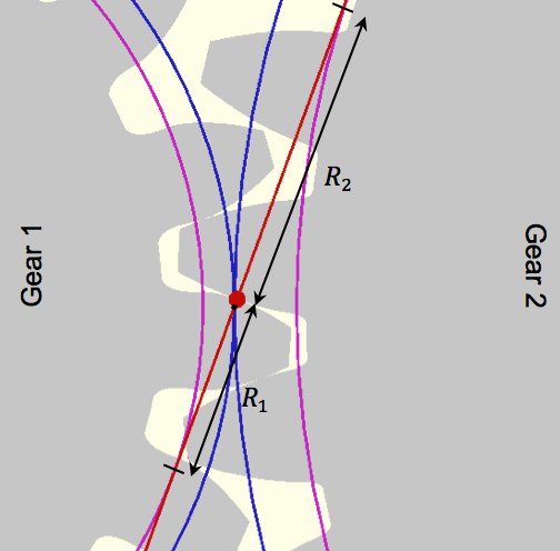
Concave surfaces (such as those of internal gears) will have a negative radius of curvature. Each of the contacting surfaces are involute in shape, and so has the useful properties that the radius of curvature of a point on the involute curve is equal to distance from that point to the base circle, measured along the pressure line:
Fig. 5: How to calculate the radii of curvature, $R_1$ and $R_2$ at a contact point.
Note that since the radii of curvatures vary on both involute profiles as the contact point moves along the line, and so the contact pressures will also vary. Therefore, it may require careful consideration of where the contact points will be. Take should be taken in making sure contact points are spaced apart even by the base pitch $p_b$, and to note the configurations at which the number of contact points change. Occasionally, for the sake of obtaining a reasonably useful value of contact stress quickly, it is possible to just consider a contact point lying at the pitch point where the pitch circles of the gears meet.
Contact pressures are useful to keep in might as excessive contact pressure can cause pitting of the gear surfaces, wearing, and fatigue.
Calculating bending stresses
The tooth forces will also cause stresses to develop at the roots of the teeth, these stresses being the bending stresses. The complex geometry of gears make it impossible to use analytical methods to figure out the bending stresses. Instead, a Finite Element Analysis should be performed. While it would seem most proper to use the Hertzian contact pressure to define the forces to be applied onto the gear model, it is more than sufficient to use a concentrated force as the force acting on the gear tooth, the magnitude and direction of which as determined in the force calculations above. Bending stresses are important to observe as excessive bending stresses can cause to fracture and loss of the tooth, resulting in sudden failure that is more difficult to gauge and predict that damage due to contact pressures.

