1
$\begingroup$

I was reading this article called "Joint Axis and Position Estimation from Inertial Measurement Data by Exploiting Kinematic Constraints", but I'm not understanding one part, which doesn't let me proceed in the reading of the same.

From the physical point of view, we have the following situation:

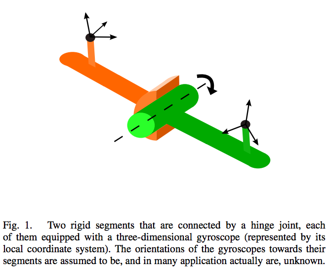
enter image description here

Two segments (one orange and the other green) connected by a hinge joint. The 3-axis coordinate systems that you see in the picture (the one on segment orange and the other on the segment green) are the local coordinate systems of two 3-dimensional gyroscopes.

The dashed line that you see in the hinge should be the coordinate axis of the same joint. Since the joint can only move in one dimension, we have just one axis.

Now, given this setting, the authors say (first page, column at the right, at the end of the same):

... let the angular velocities of the gyroscopes, in the coordinates of their local frames, be $g_1(t)$ and $g_2(t)$ for the first and the second segment, respectively. Then it is a geometrical fact, that $g_1(t)$ and $g_2(t)$ differ only by the joint angle velocity and a (time-variant) rotation matrix


Questions

  1. What is the joint angle velocity?

  2. What is this time-variant rotation matrix?

  3. Why do the angular velocities differ only by the joint angle velocity and a time-variant rotation matrix? What does it even mean, actually?
$\endgroup$

1 Answer 1

0
$\begingroup$

enter image description here

  1. What is the joint angle velocity?

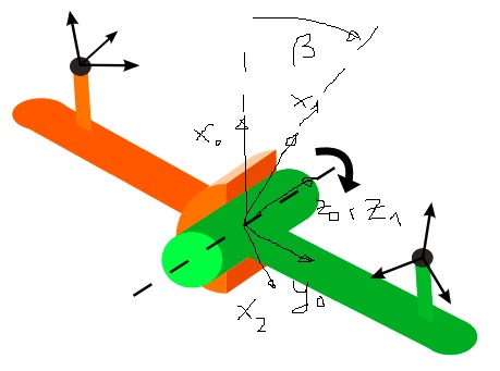
The joint angle velocity is the angular velocity of you joint, because we are acutally dealing with a 2D problem. This will become clear if you look at your system from the $z_0,z_1$ axis direction. In the picture this angular velocity is given by $\dot{\beta}$.

  1. What is this time-variant rotation matrix?

You have to consider four coordinate frames. The first coordinate frame is fixed at your joint axis $K_0=(x_0,y_0,z_0)$. The second frame is frame 1 but now rotating around the $z_0=z_1$ axis. The other two frames are there in your inital image. If you tranform from frame 1 to the other frames you will see that the rotation matrix will be time dependent. This is obvious, because depending on the time dependent motion of $\beta$ the coordinate frames will also move with time dependence.

  1. Why do the angular velocities differ only by the joint angle velocity and a time-variant rotation matrix? What does it even mean, actually?

This means that the angular velocity of the left coordinate frame $\omega_1$ and the angular velocity of the right coordinate frame $\omega_2$ are related by the angular velocity of the joint $\dot{\beta}$. The relationship is given by:

$$\omega_2-\omega_1=\dot{\beta}.$$

Note, that this simple equation is only true because we only have a 2D rotation. Imagine $\dot{\beta}=0$, then the joint is acting like a fixed link, hence the left and right coordinate frame have the same angular velocity. If $\dot{\beta}$ is positive then the angular velocity of the right frame $\omega_2$ will be the sum of the angular velocity of the left frame $\omega_1$ and the angular velocity of the joint $\dot{\beta}$.

$\endgroup$
7
  • $\begingroup$ What made every confusing, I guess, was the terminology: they actually used joint angle velocity instead of what I think it's more descriptive and less ambiguous expression (hinge) joint angular velocity. $\endgroup$
    – user11356
    Commented May 17, 2017 at 22:06
  • $\begingroup$ Just another question. The general equation incorporating both "angular velocities differ only by the joint angle velocity" and "a time-variant rotation matrix" would be something of the form $\omega_2 = \beta + R\omega_1$ (for some rotation matrix $R$), right? $\endgroup$
    – user11356
    Commented May 25, 2017 at 12:29
  • $\begingroup$ No, it should be the same as in my answer: $\omega_2=\omega_1+\dot{\beta}$. Your formula is not correct because of non-consistent dimensions. You don't need rotation matrices because the rotation is happening in one plane. $\endgroup$
    – MrYouMath
    Commented May 25, 2017 at 12:31
  • $\begingroup$ If $R$ is a $3\times 3$ matrix, the dimensions would still be consistent. How do you incorporate the rotation, and why? $\endgroup$
    – user11356
    Commented May 25, 2017 at 12:33
  • $\begingroup$ Note that in the original paper the authors say: "If the joint angle remains constant, i.e. the links are rigidly connected, then $g_1(t) = R g_2(t)$, where $R$ is the constant rotation matrix from the second to the first sensor frame". How do you explain this? $\endgroup$
    – user11356
    Commented May 25, 2017 at 12:34

Your Answer

By clicking “Post Your Answer”, you agree to our terms of service and acknowledge you have read our privacy policy.